Theft Deterrent System (For Sedan) Ignition Switch Circuit
DESCRIPTION
WIRING DIAGRAM
INSPECTION PROCEDURE
CHECK FOR DTC
READ VALUE USING TECHSTREAM (IGNITION SWITCH)
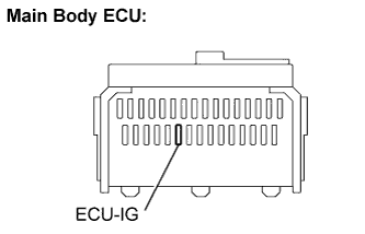
INSPECT FUSE (ECU-IG)
CHECK HARNESS OR CONNECTOR (IG POWER SOURCE)
THEFT DETERRENT SYSTEM (for Sedan) - Ignition Switch Circuit |
DESCRIPTION
When the ignition switch is turned to the ON position, the battery positive voltage is applied to terminal IG of the theft warning ECU. When the battery positive voltage is applied to terminal IG of the ECU while the theft deterrent system is operating, the warning stops. Furthermore, the power supplied from terminal IG of the ECU is used as the power for the door courtesy switch and position switch, etc.
WIRING DIAGRAM
INSPECTION PROCEDURE
Connect the Techstream to the DLC3.
Turn the ignition switch ON and turn the tester ON.
Clear the DTCs.
Check whether DTC B1269 recurs 10 seconds or more after the ignition switch is turned on.
- OK:
- No DTC is output.
| 2.READ VALUE USING TECHSTREAM (IGNITION SWITCH) |
Connect the Techstream to the DLC3.
Turn the ignition switch to ON.
Turn the tester main switch ON.
Select the item below in the Data List and read the display on Techstream.
- Theft Warning ECU:
Item
| Measurement Item/Display (Range)
| Normal Condition
| Diagnostic Note
|
IG SW
| Ignition switch signal ON/OFF
| ON: Key is in ON or START position
OFF: Key is in LOCK or ACC position
| -
|
| OK |
|
|
|
| PROCEED TO NEXT CIRCUIT INSPECTION SHOWN IN PROBLEM SYMPTOMS TABLE |
|
Remove the ECU-IG fuse from the main body ECU.
Measure the resistance.
- Standard resistance:
- Below 1 Ω
Reinstall the ECU-IG fuse.
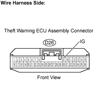
| 4.CHECK HARNESS OR CONNECTOR (IG POWER SOURCE) |
Disconnect the D26 theft warning ECU connector.
Turn the ignition switch ON.
Measure the voltage.
- Standard voltage:
Tester Connection
| Specified Condition
|
D26-9 (IG) - Body ground
| 11 to 14 V
|
Reconnect the theft warning ECU connector.
| | REPAIR OR REPLACE HARNESS OR CONNECTOR |
|
|