Theft Deterrent System (For Sedan) Security Horn Circuit
DESCRIPTION
WIRING DIAGRAM
INSPECTION PROCEDURE
PERFORM ACTIVE TEST USING TECHSTREAM (SECURITY HORN)
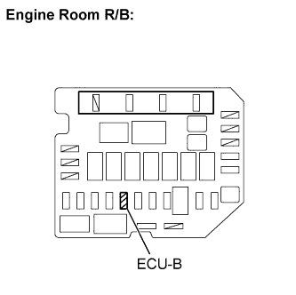
INSPECT FUSE (ECU-B)
CHECK HARNESS AND CONNECTOR (THEFT WARNING ECU ASSEMBLY- BODY GROUND)
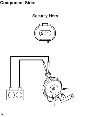
INSPECT SECURITY HORN ASSEMBLY
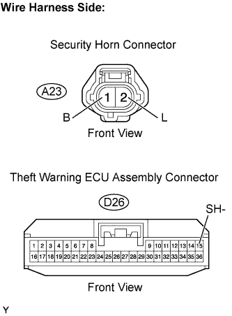
CHECK HARNESS AND CONNECTOR (THEFT WARNING ECU ASSEMBLY - SECURITY HORN ASSEMBLY)
THEFT DETERRENT SYSTEM (for Sedan) - Security Horn Circuit |
DESCRIPTION
When the theft deterrent system is changed from the armed state to the alarm sounding state, the theft warning ECU can sound the security horn. The horn cycles between ON and OFF at intervals of approximately 0.4 seconds.
WIRING DIAGRAM
INSPECTION PROCEDURE
| 1.PERFORM ACTIVE TEST USING TECHSTREAM (SECURITY HORN) |
Connect the Techstream to the DLC3.
Turn the ignition switch to ON.
Turn the tester main switch ON.
Select the item below in the Active Test and then check that the horn operate.
- Theft Warning ECU:
Item
| Test Details
| Diagnostic Note
|
Security Horn
| Security horn ON/OFF
| -
|
- OK:
- Security horn operates normally.
| OK |
|
|
|
| PROCEED TO NEXT CIRCUIT INSPECTION SHOWN IN PROBLEM SYMPTOMS TABLE |
|
Remove the ECU-B fuse from the engine room R/B.
Measure the resistance.
- Standard resistance:
- Below 1 Ω
Reinstall the ECU-B fuse.
| 3.CHECK HARNESS AND CONNECTOR (THEFT WARNING ECU ASSEMBLY- BODY GROUND) |
Disconnect the D26 theft warning ECU connector.
Measure the voltage.
- Standard voltage:
Tester Connection
| Specified Condition
|
D26-13 (+B2) - Body ground
| 11 to 14 V
|
Reconnect the theft warning ECU connector.
| | REPAIR OR REPLACE HARNESS OR CONNECTOR |
|
|
| 4.INSPECT SECURITY HORN ASSEMBLY |
Disconnect the A23 security horn connector.
Check the operation of the security horn.
- Standard:
Measurement Condition
| Specified Condition
|
Battery positive (+) → Terminal 1 (B)
Battery negative (-) → Terminal 2 (L)
| Security horn sounds
|
Reconnect the security horn connector.
| 5.CHECK HARNESS AND CONNECTOR (THEFT WARNING ECU ASSEMBLY - SECURITY HORN ASSEMBLY) |
Disconnect the D26 theft warning ECU and the A23 security horn connectors.
Measure the resistance.
- Standard resistance:
Tester Connection
| Specified Condition
|
D26-15 (SH-) - A23-1 (B)
| Below 1 Ω
|
A23-2 (L) - Body ground
| Below 1 Ω
|
D26-15 (SH-) or A23-1 (B) - Body ground
| 10 kΩ or higher
|
Reconnect the theft warning ECU and the security horn connectors.
| | REPAIR OR REPLACE HARNESS OR CONNECTOR |
|
|