Engine Immobiliser System (For Sedan) Door Courtesy Switch Circuit
DESCRIPTION
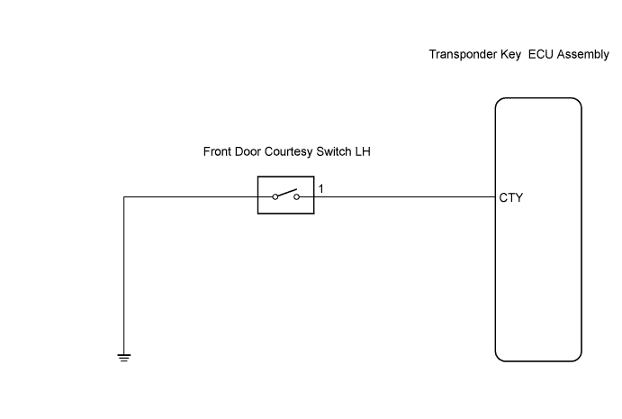
WIRING DIAGRAM
INSPECTION PROCEDURE
INSPECT FRONT DOOR COURTESY SWITCH ASSEMBLY
CHECK HARNESS AND CONNECTOR (FRONT DOOR COURTESY SWITCH CIRCUIT)
ENGINE IMMOBILISER SYSTEM (for Sedan) - Door Courtesy Switch Circuit |
DESCRIPTION
When an additional transponder key is registered, the transponder key ECU assembly detects the front door courtesy light switch open/closed condition to register the key.
WIRING DIAGRAM
INSPECTION PROCEDURE
| 1.INSPECT FRONT DOOR COURTESY SWITCH ASSEMBLY |
Remove the driver side front door courtesy switch.
Measure the resistance.
- Standard resistance:
Tester Connection
| Condition
| Specified Condition
|
1 - Switch body
| Switch pressed
| 10 kΩ or higher
|
1 - Switch body
| Switch free
| Below 1 Ω
|
Reinstall the driver side front door courtesy switch.
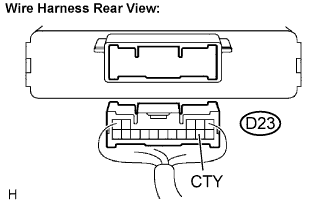
| 2.CHECK HARNESS AND CONNECTOR (FRONT DOOR COURTESY SWITCH CIRCUIT) |
Disconnect the D23 ECU connector.
Measure the resistance.
- Standard resistance:
Tester Connection
| Condition
| Specified Condition
|
D23-7 (CTY) - Body ground
| Courtesy switch pushed
| 10 kΩ or higher
|
D23-7 (CTY) - Body ground
| Courtesy switch free
| Below 1 Ω
|
Reconnect the ECU connector.
| | REPAIR OR REPLACE HARNESS OR CONNECTOR |
|
|
| OK |
|
|
|
| PROCEED TO NEXT CIRCUIT INSPECTION SHOWN IN PROBLEM SYMPTOMS TABLE |
|