Dtc B2797 Communication Malfunction No. 1
DESCRIPTION
WIRING DIAGRAM
INSPECTION PROCEDURE
CHECK KEYS
CHECK DTC
CHECK TRANSPONDER KEY ECU ASSEMBLY
CHECK HARNESS AND CONNECTOR (TRANSPONDER KEY ECU - TRANSPONDER KEY AMPLIFIER)
REPLACE TRANSPONDER KEY AMPLIFIER
DTC B2797 Communication Malfunction No. 1 |
DESCRIPTION
This DTC is output when a communication error occurs between the transponder key amplifier and transponder key ECU. Some possible reasons for the communication error are: 1) 2 or more ignition keys are positioned too close together, or 2) noise is occurring in the communication line.DTC No.
| DTC Detection Condition
| Trouble Area
|
B2797
| Keys are positioned too close to each other, or noise occurred in communication line
| - Key
- Wire harness
- Transponder key amplifier
- Transponder key ECU assembly
|
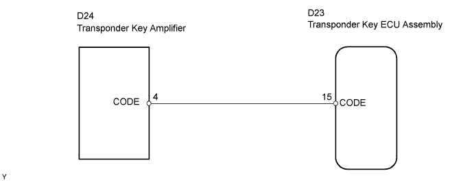
WIRING DIAGRAM
INSPECTION PROCEDURE
Check if the ignition key being used is near other ignition keys, as shown in the illustration. Also, check if the key ring is in contact with the key grip.
- Result:
Result
| Proceed to
|
The key is near other keys and/or the key ring is in contact with the key grip.
| A
|
The key is not near other keys and/or the key ring is not in contact with the key grip.
| B
|
Separate the keys from each other and/or remove the key ring.
Delete the DTC (YARIS_NCP93 RM0000012F000PX.html).
Insert a key into the ignition cylinder. Remove it. Repeat for all the other keys.
Check that no code is output.
- OK:
- No code is output.
| OK |
|
|
|
| END (INSPECTION FINISHED) |
|
| 3.CHECK TRANSPONDER KEY ECU ASSEMBLY |
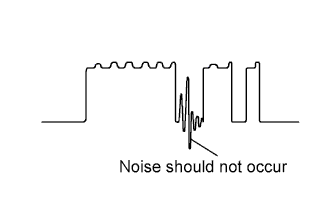
Using an oscilloscope or the Techstream, check for noise in the waveform between the terminals of the D24 transponder key amplifier connector and D23 transponder key ECU connector.
- Result:
Tester Connection
| Specified Condition
|
D23-15 (CODE) - D24-4 (CODE)
| No noise is occur
|
Tool Setting
| 5 V/DIV., 20 ms/DIV.
|
Condition
| Ignition switch
OFF →
ON
|
| | FIND CAUSE OF NOISE AND REMOVE IT |
|
|
| 4.CHECK HARNESS AND CONNECTOR (TRANSPONDER KEY ECU - TRANSPONDER KEY AMPLIFIER) |
Disconnect the D23 transponder key ECU connector.
Disconnect the D24 transponder key amplifier connector.
Measure the resistance of the wire harness side connectors.
- Standard resistance:
Tester Connection
| Specified Condition
|
D23-15 (CODE) - D24-4 (CODE)
| Below 1 Ω
|
Reconnect the D23 transponder key ECU connector.
Reconnect the D24 transponder amplifier connector.
| | REPAIR OR REPLACE HARNESS OR CONNECTOR |
|
|
| 5.REPLACE TRANSPONDER KEY AMPLIFIER |
After replacing the transponder key amplifier with a normally functioning amplifier, check that the engine starts.
- OK:
- Engine starts.
| OK |
|
|
|
| END (TRANSPONDER KEY AMPLIFIER DEFECTIVE) |
|