Power Door Lock Control System (For Hatchback) Only Back Door Cannot Be Opened
DESCRIPTION
WIRING DIAGRAM
INSPECTION PROCEDURE
READ VALUE USING TECHSTREAM (DOOR LOCK STATUS)
PERFORM ACTIVE TEST USING TECHSTREAM
READ VALUE USING TECHSTREAM
INSPECT BACK DOOR LOCK ASSEMBLY
CHECK HARNESS AND CONNECTOR (BACK DOOR LOCK ASSEMBLY - INSTRUMENT PANEL JUNCTION BLOCK ASSEMBLY)
INSPECT INSTRUMENT PANEL JUNCTION BLOCK ASSEMBLY
INSPECT BACK DOOR OPENER SWITCH ASSEMBLY
CHECK HARNESS AND CONNECTOR (MAIN BODY ECU - BACK DOOR OPENER SWITCH ASSEMBLY)
POWER DOOR LOCK CONTROL SYSTEM (for Hatchback) - Only Back Door cannot be Opened |
DESCRIPTION
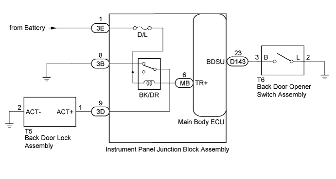
The main body ECU receives signals from the back door opener switch assembly. Then, the main body ECU activates the back door lock motor.
WIRING DIAGRAM
INSPECTION PROCEDURE
| 1.READ VALUE USING TECHSTREAM (DOOR LOCK STATUS) |
Unlock all doors.
Connect the Techstream to the DLC3.
Turn the ignition switch to ON.
Turn the Techstream on.
Enter the following menus: Body Electrical / Main Body / Data List.
According to the display on the Techstream, read the Data List.
Main BodyTester Display
| Measurement Item/Range
| Normal Condition
| Diagnostic Note
|
Back Door Open
| Back door open status / Prohibit or Permit
| Prohibit: Back door locked
Permit: Back door unlocked
| -
|
- OK:
- The Techstream indicates Permit according to the door lock operation shown in the table.
| 2.PERFORM ACTIVE TEST USING TECHSTREAM |
Connect the Techstream to the DLC3.
Turn the ignition switch to ON.
Turn the Techstream on.
Enter the following menus: Body Electrical / Main Body / Active Test.
According to the display on the Techstream, perform the Active Test.
Main BodyTester Display
| Test Part
| Control Range
| Diagnostic Note
|
Trunk and Back-Door Open
| Back door lock motor
| OFF / ON
| -
|
- OK:
- The back door lock assembly unlatches when ON is selected.
| 3.READ VALUE USING TECHSTREAM |
Connect the Techstream to the DLC3.
Turn the ignition switch to ON.
Turn the Techstream on.
Enter the following menus: Body Electrical / Main Body / Data List.
According to the display on the Techstream, read the Data List.
Main BodyTester Display
| Measurement Item/Range
| Normal Condition
| Diagnostic Note
|
Back Door Open Handle SW
| Back door opener switch signal / OFF or ON
| OFF: Back door opener switch not pushed
ON: Back door opener switch pushed
| -
|
- OK:
- The Techstream indicates ON or OFF according to the switch operation shown in the table.
| 4.INSPECT BACK DOOR LOCK ASSEMBLY |
Inspect the back door lock assembly (YARIS_NCP93 RM000001Y80035X.html).
| 5.CHECK HARNESS AND CONNECTOR (BACK DOOR LOCK ASSEMBLY - INSTRUMENT PANEL JUNCTION BLOCK ASSEMBLY) |
Disconnect the T5 back door lock assembly connector.
Disconnect the 3D instrument panel junction block assembly connector.
Measure the resistance according to the value(s) in the table below.
- Standard Resistance:
Tester Connection
| Condition
| Specified Condition
|
T5-1 (ACT+) - 3D-9
| Always
| Below 1 Ω
|
T5-2 (ACT-) - Body ground
| Always
| Below 1 Ω
|
T5-1 (ACT+) - Body ground
| Always
| 10 kΩ or higher
|
| | REPAIR OR REPLACE HARNESS OR CONNECTOR |
|
|
| 6.INSPECT INSTRUMENT PANEL JUNCTION BLOCK ASSEMBLY |
Text in Illustration*a
| Component without harness connected
(Instrument Panel Junction Block Assembly)
| -
| -
|
Remove the instrument panel junction block assembly (YARIS_NCP93 RM000003TOE00CX.html).
Remove the main body ECU (YARIS_NCP93 RM000003TOE00CX.html).
Measure the resistance according to the value(s) in the table below.
- Standard Resistance:
Tester Connection
| Condition
| Specified Condition
|
3E-1 - 3D-9
| Always
| 10 kΩ or higher
|
3E-1 - MB-6 (TR+)
| Always
| Below 1 Ω
|
Measure the voltage according to the value(s) in the table below.
- Standard Voltage:
Tester Connection
| Condition
| Specified Condition
|
3D-9 - Body ground
| Battery positive (+) → 3E-1
Battery negative (-) → MB-6
| 11 to 14 V
|
| 7.INSPECT BACK DOOR OPENER SWITCH ASSEMBLY |
Inspect the back door opener switch assembly (YARIS_NCP93 RM000002QPK01LX.html).
| 8.CHECK HARNESS AND CONNECTOR (MAIN BODY ECU - BACK DOOR OPENER SWITCH ASSEMBLY) |
Disconnect the D143 main body ECU connector.
Measure the resistance according to the value(s) in the table below.
- Standard Resistance:
Tester Connection
| Condition
| Specified Condition
|
D143-23 (BDSU) - T6-3 (B)
| Always
| Below 1 Ω
|
T6-2 (L) - Body ground
| Always
| Below 1 Ω
|
T6-3 (B) - Body ground
| Always
| 10 kΩ or higher
|
| | REPAIR OR REPLACE HARNESS OR CONNECTOR |
|
|