Vehicle Interior. Yaris. Ncp93, 131
Door Lock. Yaris. Ncp93, 131
Power Door Lock Control System (For Hatchback) -- Terminals Of Ecu |
| CHECK INSTRUMENT PANEL JUNCTION BLOCK ASSEMBLY AND MAIN BODY ECU |
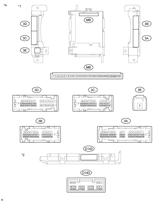
| *A | Main Body ECU 1 Connector Type | - | - |
| *1 | Instrument Panel Junction Block Assembly | *2 | Main Body ECU |
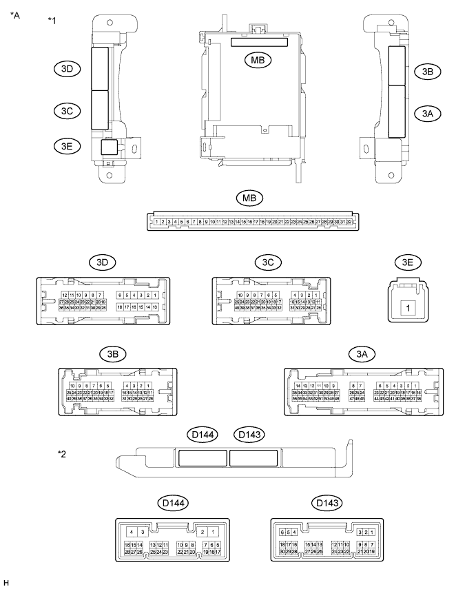
| *A | Main Body ECU 2 Connector Type | - | - |
| *1 | Instrument Panel Junction Block Assembly | *2 | Main Body ECU |
Remove the main body ECU from the instrument panel junction block assembly.
Measure the resistance and voltage between each terminal of the wire harness side connectors and body ground.
Terminal No. (Symbol) Wiring Color Terminal Description Condition Specified Condition MB-11 (GND1) - Body ground None - Body ground Ground Always Below 1 Ω MB-30 (BECU) - Body ground None - Body ground Battery power supply Always 11 to 14 V MB-32 (IG) - Body ground None - Body ground Ignition switch power supply Ignition switch ON 11 to 14 V Ignition switch off Below 1 V MB-29 (ACC) - Body ground None - Body ground ACC power supply Ignition switch ACC 11 to 14 V Ignition switch off Below 1 V Install the main body ECU to the instrument panel junction block assembly.
Measure the voltage and resistance, check for pulse according to the value(s) in the table below.
Terminal No. (Symbol) Wiring Color Terminal Description Condition Specified Condition 3D-36 (FLCY) - Body ground L - Body ground Front door LH courtesy light switch input Front door LH open Below 1 V Front door LH closed Pulse generation D143-19 (FRCY) - Body ground Y - Body ground Front door RH courtesy light switch input Front door RH open Below 1 V Front door RH closed Pulse generation D143-6 (LRCY) - Body ground*1 G - Body ground Rear door courtesy light switch input Rear door LH or RH open Below 1 V Rear door LH and RH closed Pulse generation D143-1 (BCTY) - Body ground*2 B - Body ground Back door courtesy light switch input Back door open Below 1 V Back door closed 11 to 14 V 3D-35 (BCTY) - Body ground*3 B - Body ground Back door courtesy light switch input Back door open Below 1 V Back door closed 11 to 14 V D143-17 (KSW) - Body ground Y - Body ground Unlock warning switch input No key in ignition key cylinder (off) 10 kΩ or higher Key inserted (on) Below 1 Ω D143-11 (L2) - Body ground B - Body ground Driver door lock and unlock switch input Driver door key cylinder in lock position Below 1 V Driver door key cylinder in neutral position Pulse generation D143-12 (UL2) - Body ground G - Body ground Front passenger door lock and unlock switch input Front passenger door key cylinder in unlock position Below 1 V Front passenger door key cylinder in neutral position Pulse generation D143-24 (UL3) - Body ground G - Body ground Driver door lock and unlock switch input Driver door key cylinder in unlock position Below 1 V Driver door key cylinder in neutral position Pulse generation 3B-2 (ACT+) - Body ground V - Body ground Door lock motor lock drive output (for front RH side) Door control switch not pushed and front door key cylinder in neutral position Below 1 V Lock side of door control switch pushed or front door key cylinder in lock position 11 to 14 V 3B-1 (ACT+) - Body ground Y - Body ground Door lock motor lock drive output (for front LH side) Door control switch not pushed and front door key cylinder in neutral position Below 1 V Lock side of door control switch pushed or front door key cylinder in lock position 11 to 14 V 3D-12 (ACT+) - Body ground*1 L - Body ground Door lock motor lock drive output (for rear RH side) Door control switch not pushed and front door key cylinder in neutral position Below 1 V Lock side of door control switch pushed or front door key cylinder in lock position 11 to 14 V 3D-11 (ACT+) - Body ground*1 GR - Body ground Door lock motor lock drive output (for rear LH side) Door control switch not pushed and front door key cylinder in neutral position Below 1 V Lock side of door control switch pushed or front door key cylinder in lock position 11 to 14 V 3D-9 (TR+) - Body ground Y - Body ground Door lock motor lock drive output (for back door) Back door closed 11 to 14 V Back door opener - switch pushed Below 1 V 3B-3 (ACT-) - Body ground R - Body ground Door lock motor unlock drive output (for front RH side) Door control switch not pushed and front door key cylinder in neutral position Below 1 V Unlock side of door control switch pushed or front door key cylinder in unlock position 11 to 14 V 3B-4 (ACTD) - Body ground L - Body ground Door lock motor unlock drive output (for front LH side) Door control switch not pushed and door key cylinder in neutral position Below 1 V Unlock side of door control switch pushed or front door key cylinder in unlock position 11 to 14 V 3D-8 (ACT-) - Body ground*1 P - Body ground Door lock motor unlock drive output (for rear RH side) Door control switch not pushed and front door key cylinder in neutral position Below 1 V Unlock side of door control switch pushed or front door key cylinder in unlock position 11 to 14 V 3D-7 (ACT-) - Body ground*1 LG - Body ground Door lock motor unlock drive output (for rear LH side) Door control switch not pushed and front door key cylinder in neutral position Below 1 V Unlock side of door control switch pushed or front door key cylinder in unlock position 11 to 14 V D143-18 (LSFR) - Body ground LG - Body ground Front door RH unlock detection switch input Front door RH unlocked Below 1 V Front door RH locked Pulse generation D143-7 (LSFL) - Body ground L - Body ground Front door LH unlock detection switch input Front door LH unlocked Below 1 V Front door LH locked Pulse generation 3D-25 (LSR) - Body ground*1*4 V - Body ground Rear door RH unlock detection switch input Rear door RH or LH unlocked Below 1 V Rear door RH and LH locked Pulse generation 3D-24 (LSR) - Body ground*1*4 Y - Body ground Rear door LH unlock detection switch input Rear door LH or RH unlocked Below 1 V Rear door LH and RH locked Pulse generation - *1: for 5 Door
- *2: w/o Daytime Running Light System and w/o Theft Deterrent System
- *3: w/ Daytime Running Light System or w/ Theft Deterrent System
- *4: w/ Theft Deterrent System
- *1: for 5 Door