Power Door Lock Control System (For Sedan) Key Lock-In Prevention Function Does Not Work Properly
DESCRIPTION
WIRING DIAGRAM
INSPECTION PROCEDURE
READ VALUE USING TECHSTREAM
READ VALUE USING TECHSTREAM
INSPECT UNLOCK WARNING SWITCH ASSEMBLY
CHECK HARNESS AND CONNECTOR (UNLOCK WARNING SWITCH ASSEMBLY - MAIN BODY ECU)
INSPECT FRONT DOOR COURTESY SWITCH ASSEMBLY (DRIVER SIDE)
CHECK HARNESS AND CONNECTOR (FRONT DOOR COURTESY SWITCH - MAIN BODY ECU)
POWER DOOR LOCK CONTROL SYSTEM (for Sedan) - Key Lock-in Prevention Function does not Work Properly |
DESCRIPTION
When the key is in the ignition key cylinder or the door courtesy light ON signal is output to the main body ECU, performing the door lock operation with the lock switch does not lock the doors.- HINT:
- Since the key reminder warning system has functions that use CAN communication, firstly confirm that there is no malfunction in the communication system by inspecting the CAN communication functions in accordance with How to Proceed with Troubleshooting. Then, conduct the following troubleshooting procedure.
WIRING DIAGRAM
INSPECTION PROCEDURE
| 1.READ VALUE USING TECHSTREAM |
Connect a Techstream to the DLC3.
Turn the ignition switch to ON.
Turn the tester on.
Enter the following menus: Body Electrical / Main Body / Data List.
According to the display on tester, read on the "Data List".
- Main Body:
Tester Display
| Measurement Item/Range
| Normal Condition
| Diagnostic Note
|
D Door Courtesy SW
| Driver side door courtesy switch signal / ON or OFF
| ON: Driver side door is open
OFF: Driver side door is closed
| -
|
- OK:
- The display is as specified in the normal condition.
| 2.READ VALUE USING TECHSTREAM |
Connect a Techstream to the DLC3.
Turn the ignition switch to ON.
Turn the tester on.
Enter the following menus: Body Electrical / Main Body / Data List.
According to the display on tester, read on the "Data List".
- Main Body:
Tester Display
| Measurement Item/Range
| Normal Condition
| Diagnostic Note
|
Key Unlock Warning SW
| Unlock warning switch signal / ON or OFF
| ON: Key is in ignition key cylinder
OFF: No key is in ignition key cylinder
| -
|
- OK:
- The display is as specified in the normal condition.
| 3.INSPECT UNLOCK WARNING SWITCH ASSEMBLY |
Remove the unlock warning switch assembly.
Measure the resistance.
- Standard resistance:
Tester Connection
| Condition
| Specified Condition
|
1 - 2
| Not pushed
| 10 kΩor higher
|
1 - 2
| Pushed
| Below 1 Ω
|
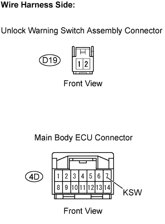
| 4.CHECK HARNESS AND CONNECTOR (UNLOCK WARNING SWITCH ASSEMBLY - MAIN BODY ECU) |
Disconnect the D19 unlock warning switch connector.
Disconnect the 4D main body ECU connector.
Measure the resistance.
- Standard resistance:
Tester Connection
| Specified Condition
|
D19-1 - 4D-7 (KSW)
| Below 1 Ω
|
D19-2 - Body ground
| Below 1 Ω
|
Reconnect the unlock warning switch connector.
Reconnect the main body ECU connector.
| | REPAIR OR REPLACE HARNESS OR CONNECTOR |
|
|
| 5.INSPECT FRONT DOOR COURTESY SWITCH ASSEMBLY (DRIVER SIDE) |
Remove the door courtesy switch.
Measure the resistance.
- Standard resistance:
Tester Connection
| Condition
| Specified Condition
|
1 - Body ground
| Not pushed (ON)
| Below 1 Ω
|
1 - Body ground
| Pushed (OFF)
| 10 kΩor higher
|
Reinstall the courtesy switch.
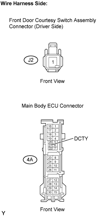
| 6.CHECK HARNESS AND CONNECTOR (FRONT DOOR COURTESY SWITCH - MAIN BODY ECU) |
Disconnect the J2 door courtesy switch connector.
Disconnect the 4A main body ECU connector.
Measure the resistance.
- Standard resistance:
Tester Connection
| Specified Condition
|
J2-1 - 4A-21 (DCTY)
| Below 1 Ω
|
Reconnect the door courtesy switch connector.
Reconnect the main body ECU connector.
| | REPAIR OR REPLACE HARNESS OR CONNECTOR |
|
|