Generator (For Hatchback) -- Reassembly |
| 1. INSTALL GENERATOR ROTOR ASSEMBLY |
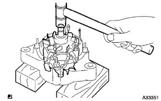 |
Place the generator rotor assembly on the generator drive end frame assembly.
Using a plastic hammer, install the generator rotor assembly to the generator drive end frame assembly.
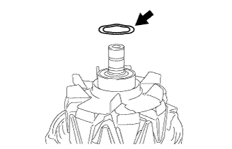
Install a new generator washer on the generator rotor assembly.
 |
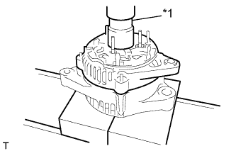
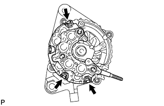
Using a 30 mm/12 pt socket wrench and press, slowly press in the generator rectifier end frame.
Text in Illustration *1 30 mm/ 12 pt Socket Wrench
 |
Install the 3 nuts A.
- Torque:
- 4.5 N*m{46 kgf*cm, 40 in.*lbf}
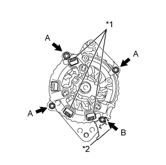 |
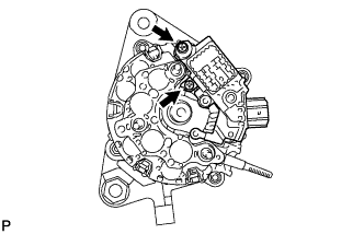
Install the 3 terminal insulators onto the generator rectifier end frame.
Install the cord clip with the nut B.
- Torque:
- 5.4 N*m{55 kgf*cm, 48 in.*lbf}
Text in Illustration *1 Terminal Insulator *2 Cord Clip
| 2. INSTALL GENERATOR HOLDER WITH RECTIFIER |
 |
Install the generator holder with rectifier with the 3 screws.
- Torque:
- 2.0 N*m{20 kgf*cm, 18 in.*lbf}
| 3. INSTALL GENERATOR REGULATOR ASSEMBLY |
 |
Install the generator regulator assembly with the 2 screws.
- Torque:
- 2.0 N*m{20 kgf*cm, 18 in.*lbf}
| 4. INSTALL GENERATOR BRUSH HOLDER ASSEMBLY |
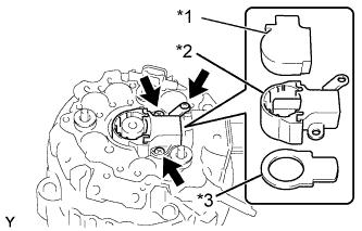 |
Install the generator plate seal.
Install the generator brush holder assembly with the 3 screws.
- Torque:
- 2.0 N*m{20 kgf*cm, 18 in.*lbf}
Install the generator brush cover onto the generator brush holder assembly.
Text in Illustration *1 Generator Brush Cover *2 Generator Brush Holder Assembly *3 Generator Plate Seal
Install the generator rear end cover with the 2 nuts B.
- Torque:
- Nut B:
- 4.4 N*m{45 kgf*cm, 39 in.*lbf}
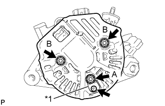 |
Install the rectifier plate with the nut A and screw.
- Torque:
- Nut A:
- 4.4 N*m{45 kgf*cm, 39 in.*lbf}
- Screw:
- 3.9 N*m{40 kgf*cm, 35 in.*lbf}
Text in Illustration *1 Rectifier Plate
| 5. INSTALL GENERATOR TERMINAL INSULATOR |
Install the generator terminal insulator with the nut.
- Torque:
- 4.1 N*m{42 kgf*cm, 36 in.*lbf}
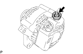 |
| 6. INSTALL GENERATOR PULLEY |
 |
Clamp the generator housing stay in a vise tightly.
Install the generator pulley onto the generator rotor shaft by tightening the generator pulley nut by hand.
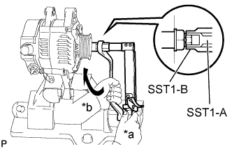
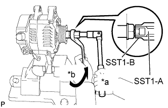
Hold SST1-A with a torque wrench, and tighten SST1-B clockwise to the specified torque.
- SST
- 09820-63011(09820-06010,09820-06021)
- Torque:
- 64 N*m{653 kgf*cm, 47 ft.*lbf}
Text in Illustration *a Hold *b Turn - NOTICE:
- Check that SST is securely fitted onto the generator rotor shaft.
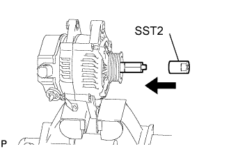
Insert SST2, and engage SST2 to the pulley nut.
 |
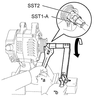
Tighten the generator pulley nut by turning SST1-A in the direction shown in the illustration.
Text in Illustration *a Hold *b Turn - Torque:
- 133 N*m{1356 kgf*cm, 98 ft.*lbf}
- HINT:
- Hold the adjustable wrench against the vise and tighten the nut securely.
 |
Remove SST 2 from the generator assembly.
Hold SST1-A, turn SST1-B, and remove SST1-A and SST1-B from the generator assembly.
Text in Illustration *a Hold *b Turn
 |
Turn the generator pulley, and check that the generator pulley moves smoothly.
Remove the generator assembly from a vise.