Steering Column Assembly (For Hatchback) Removal
PRECAUTION
POSITION FRONT WHEELS FACING STRAIGHT AHEAD
DISCONNECT CABLE FROM NEGATIVE BATTERY TERMINAL
REMOVE STEERING PAD
REMOVE STEERING WHEEL ASSEMBLY
REMOVE LOWER STEERING COLUMN COVER
REMOVE UPPER STEERING COLUMN COVER
REMOVE COMBINATION SWITCH ASSEMBLY
REMOVE BRAKE PEDAL SUPPORT SUB-ASSEMBLY
REMOVE COLUMN HOLE COVER SILENCER SHEET
REMOVE STEERING SLIDING YOKE SUB-ASSEMBLY
REMOVE STEERING COLUMN ASSEMBLY
Steering Column Assembly (For Hatchback) -- Removal |
- CAUTION:
- Some of these service operations affect the SRS airbag system. Read the precautionary notices concerning the SRS airbag system before servicing (YARIS_NCP93 RM000000KT10EAX.html).
- NOTICE:
- After turning the ignition switch off, waiting time may be required before disconnecting the cable from the battery terminal. Therefore, make sure to read the disconnecting the cable from the battery terminal notice before proceeding with work (YARIS_NCP93 RM00000482L007X.html).
| 2. POSITION FRONT WHEELS FACING STRAIGHT AHEAD |
| 3. DISCONNECT CABLE FROM NEGATIVE BATTERY TERMINAL |
- CAUTION:
- Wait at least 90 seconds after disconnecting the cable from the negative (-) battery terminal to disable the SRS system.
(YARIS_NCP93 RM000000V6N02JX.html)
| 5. REMOVE STEERING WHEEL ASSEMBLY |
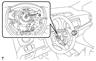
Remove the steering wheel assembly set nut.
Put matchmarks on the steering wheel assembly and the steering main shaft.
Text in Illustration*a
| Matchmark
|
Disconnect the connectors from the spiral cable.
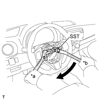
Using SST, remove the steering wheel assembly.
- SST
- 09950-50013(09951-05010,09952-05010,09953-05020,09954-05021)
Text in Illustration*a
| Hold
|
*b
| Turn
|
- NOTICE:
- Apply a small amount of grease to the threads and tip of SST (center bolt) before use.
| 6. REMOVE LOWER STEERING COLUMN COVER |
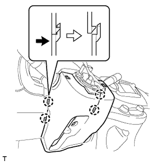
Remove the 3 screws.
Disengage the 4 claws and remove the lower steering column cover.
| 7. REMOVE UPPER STEERING COLUMN COVER |
Disengage the claw and remove the upper steering column cover.
| 8. REMOVE COMBINATION SWITCH ASSEMBLY |
Disconnect all connectors from the combination switch assembly.
Use pliers to hold the clamp and raise the claw with a screwdriver. Remove the combination switch assembly from the steering column assembly.
| 9. REMOVE BRAKE PEDAL SUPPORT SUB-ASSEMBLY |
(YARIS_NCP93 RM000001CEU01RX.html)
| 10. REMOVE COLUMN HOLE COVER SILENCER SHEET |
Remove the 2 clips and the column hole cover silencer sheet.
| 11. REMOVE STEERING SLIDING YOKE SUB-ASSEMBLY |
Place matchmarks on the No. 2 steering intermediate shaft assembly and steering column assembly.
Text in Illustration*1
| No. 2 Steering Intermediate Shaft Assembly
|
*2
| Steering Sliding Yoke Sub-assembly
|
*a
| Matchmark
|
Place matchmarks on the steering sliding yoke sub-assembly and steering gear assembly.
Loosen bolt A.
Loosen bolt C.
Remove bolt B and detach the steering sliding yoke sub-assembly from the steering gear assembly.
| 12. REMOVE STEERING COLUMN ASSEMBLY |
Separate the wire harness clamp from the power steering ECU assembly.
Disconnect the 2 steering column assembly connectors from the power steering ECU assembly.
Disconnect all connectors and detach all wire harness clamps from the steering column assembly.
Remove the bolt, 2 nuts and the steering column assembly from the instrument panel reinforcement assembly.