Dtc C1511 Torque Sensor Circuit Malfunction
DESCRIPTION
WIRING DIAGRAM
INSPECTION PROCEDURE
CHECK CONNECTOR CONNECTION CONDITION
INSPECT POWER STEERING ECU ASSEMBLY (TORQUE SENSOR OUTPUT)
INSPECT POWER STEERING ECU ASSEMBLY (TRQ1, TRQ2 VOLTAGE)
DTC C1511 Torque Sensor Circuit Malfunction |
DTC C1512 Torque Sensor Circuit Malfunction |
DTC C1513 Torque Sensor Circuit Malfunction |
DTC C1514 Torque Sensor Power Supply Abnormal |
DTC C1517 Torque Hold Abnormal |
DESCRIPTION
The torque sensor converts the rotation torque input from the steering wheel into electric signals and sends them to the power steering ECU assembly.DTC No.
| Detection Item
| Trouble Area
|
C1511
| Torque sensor (TRQ1) signal error or stop
| - Steering column assembly (Torque sensor)
- Power steering ECU assembly
|
C1512
| Torque sensor (TRQ2) signal error or stop
|
C1513
| Deviation between torque sensor TRQ1 and TRQ2 exceeds specified value
|
C1514
| Torque sensor power source voltage error
|
C1517
| Temporary control due to malfunction related to torque sensor continues for long time
|
WIRING DIAGRAM
INSPECTION PROCEDURE
- NOTICE:
- If the power steering ECU assembly or steering column assembly has been replaced, perform the torque sensor zero point calibration and assist map writing (YARIS_NCP93 RM000000OSZ018X.html).
| 1.CHECK CONNECTOR CONNECTION CONDITION |
Check the installation condition of the torque sensor connector.
- OK:
- Torque sensor connector is securely connected to the power steering ECU assembly.
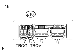
| 2.INSPECT POWER STEERING ECU ASSEMBLY (TORQUE SENSOR OUTPUT) |
Start the engine.
Measure the voltage according to the value(s) in the table below.
- Standard Voltage:
Tester Connection
| Condition
| Specified Condition
|
c10-8 (TRQV) - c10-2 (TRQG)
| Engine running
| 4.5 to 5.5 V
|
Text in Illustration*a
| Component with harness connected
(Power Steering ECU Assembly)
|
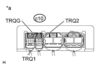
| 3.INSPECT POWER STEERING ECU ASSEMBLY (TRQ1, TRQ2 VOLTAGE) |
Start the engine.
Measure the voltage according to the value(s) in the table below.
- Standard Voltage:
Tester Connection
| Switch Condition
| Specified Condition
|
c10-9 (TRQ1) - c10-2 (TRQG)
| Engine running, steering wheel not turned (without load)
| 2.3 to 2.7 V
|
c10-9 (TRQ1) - c10-2 (TRQG)
| Engine running, steering wheel turned to right with vehicle stopped
| 2.5 to 3.8 V
|
c10-9 (TRQ1) - c10-2 (TRQG)
| Engine running, steering wheel turned to left with vehicle stopped
| 1.2 to 2.5 V
|
c10-1 (TRQ2) - c10-2 (TRQG)
| Engine running, steering wheel not turned (without load)
| 2.3 to 2.7 V
|
c10-1 (TRQ2) - c10-2 (TRQG)
| Engine running, steering wheel turned to right with vehicle stopped
| 1.2 to 2.5 V
|
c10-1 (TRQ2) - c10-2 (TRQG)
| Engine running, steering wheel turned to left with vehicle stopped
| 2.5 to 3.8 V
|
Text in Illustration*a
| Component with harness connected
(Power Steering ECU Assembly)
|
Calculate the difference between the measured TRQV*1 and the sum of the output values of the torque sensor 1 and torque sensor 2.
- HINT:
- *1: TRQV was measured in the previous step.
- OK:
- 0.3 V or less