Power Steering System (For Sedan) Eps Warning Light Circuit
DESCRIPTION
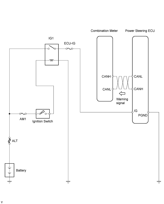
WIRING DIAGRAM
INSPECTION PROCEDURE
INSPECT CAN COMMUNICATION SYSTEM
READ VALUE USING TECHSTREAM
CHECK HARNESS AND CONNECTOR (POWER STEERING ECU - BODY GROUND)
REPLACE POWER STEERING ECU
CHECK EPS WARNING LIGHT (COMBINATION METER)
POWER STEERING SYSTEM (for Sedan) - EPS Warning Light Circuit |
DESCRIPTION
If the power steering ECU detects a malfunction, the EPS warning light comes on. At this time, the power steering ECU stores a DTC in its memory.
WIRING DIAGRAM
INSPECTION PROCEDURE
| 1.INSPECT CAN COMMUNICATION SYSTEM |
Using a Techstream, check for DTCs and confirm that there are no problems in the CAN communication system.
- OK:
- DTCs are not output.
| 2.READ VALUE USING TECHSTREAM |
Connect a Techstream to the DLC3.
Turn the ignition switch to ON.
Turn the Techstream on.
Enter the following menus: Chassis / EMPS / Data List.
Select the item "IG Power Supply" in the Data List and read the value displayed on the Techstream.
EMPS:Tester Display
| Measurement Item/Range
| Normal Condition
| Diagnostic Note
|
IG Power Supply
| ECU power source voltage: Minimum: 0.0000 V, Maximum: 20.1531 V
| 11 to 14 V: Ignition switch ON
| -
|
- OK:
- The normal condition value is displayed on the Techstream.
- HINT:
- If the voltage is not standard value, inspect the IG power source circuit.
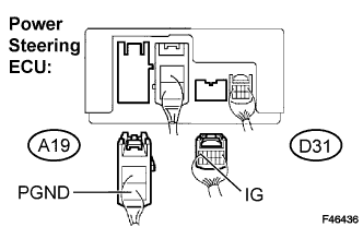
| 3.CHECK HARNESS AND CONNECTOR (POWER STEERING ECU - BODY GROUND) |
Disconnect the connectors from the power steering ECU.
Measure the voltage and the resistance.
- Standard:
Tester Connection
| Condition
| Specified Condition
|
IG (D31-6) - Body ground
| Ignition switch on
| 11 to 14 V
|
PGND (A19-2) - Body ground
| Always
| Below 1 Ω
|
| | REPAIR OR REPLACE HARNESS OR CONNECTOR |
|
|
| 4.REPLACE POWER STEERING ECU |
- NOTICE:
- After replacing the power steering ECU, perform the torque sensor zero point calibration.
| 5.CHECK EPS WARNING LIGHT (COMBINATION METER) |
Check that the EPS warning light on the combination meter does not come on.
- OK:
- The EPS warning light does not come on.