Dtc C1524/24 Motor Circuit Malfunction
DESCRIPTION
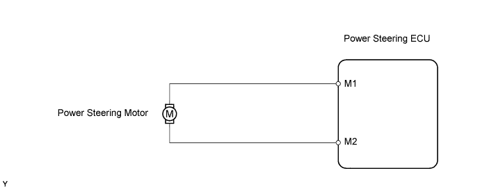
WIRING DIAGRAM
INSPECTION PROCEDURE
READ VALUE USING TECHSTREAM
INSPECT POWER STEERING ECU
CHECK HARNESS AND CONNECTOR (POWER STEERING ECU - BODY GROUND)
INSPECT STEERING COLUMN ASSEMBLY (POWER STEERING MOTOR)
DTC C1524/24 Motor Circuit Malfunction |
DESCRIPTION
The power steering ECU supplies the current to the power steering motor through the motor circuit.DTC No.
| DTC Detection Condition
| Trouble Area
|
C1524/24
| Short (or open) in motor circuit or abnormal voltage or current in motor circuit.
| - Steering column assembly
- Power steering ECU
|
WIRING DIAGRAM
INSPECTION PROCEDURE
| 1.READ VALUE USING TECHSTREAM |
Connect a Techstream to the DLC3.
Turn the ignition switch to ON.
Turn the Techstream on.
Enter the following menus: Chassis / EMPS / Data List.
Select the item "Motor Actual Current" and "Command Value Current" in the Data List and read the value displayed on the Techstream.
Standard current:Data List Item
| Steering Position
(Left Turned)
| Steering Position
(Center)
| Steering Position
(Right Turned)
|
Motor Actual Current
| 10 A to 55 A
| -1 A to +1 A
| -55 A to -10 A
|
Command Value Current
| 55 A
| 0 A
| -55 A
|
- HINT:
- The current changes when steering wheel is turned.
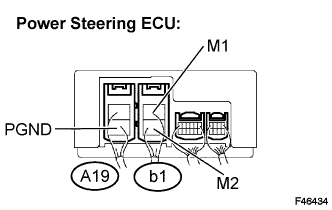
| 2.INSPECT POWER STEERING ECU |
Turn the ignition switch to ON.
Measure the voltage.
- Standard voltage:
Tester Connection
| Condition
(Steering Position)
| Specified Condition
|
M1 (b1-1) - PGND (A19-2)
| Turned to right
| Below 1 V
|
M1 (b1-1) - PGND (A19-2)
| Turned to left
| 11 to 14 V
|
M2 (b1-2) - PGND (A19-2)
| Turned to right
| 11 to 14 V
|
M2 (b1-2) - PGND (A19-2)
| Turned to left
| Below 1 V
|
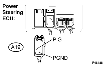
| 3.CHECK HARNESS AND CONNECTOR (POWER STEERING ECU - BODY GROUND) |
Disconnect the connector from the power steering ECU.
Measure the resistance and the voltage.
- Standard:
Tester Connection
| Condition
| Specified Condition
|
PGND (A19-2) - Body ground
| Always
| Below 1 Ω
|
PIG (A19-1) - Body ground
| Ignition switch on.
| 11 to 14 V
|
| | REPAIR OR REPLACE HARNESS OR CONNECTOR |
|
|
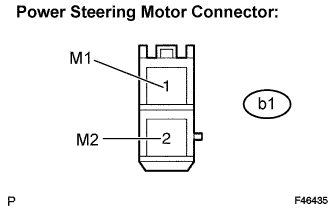
| 4.INSPECT STEERING COLUMN ASSEMBLY (POWER STEERING MOTOR) |
Disconnect the connector from the power steering ECU.
Measure the resistance.
- Standard resistance:
Tester Connection
| Condition
| Specified Condition
|
M1 (b1-1) - M2 (b1-2)
| Always
| 0.08 to 0.15 Ω
|
M1 (b1-1) - Body ground
| Always
| 1 MΩ or higher
|
M2 (b1-2) - Body ground
| Always
| 1 MΩ or higher
|