Parking Brake Lever (For Sedan) Installation
INSTALL PARKING BRAKE SWITCH
INSTALL PARKING BRAKE LEVER
INSTALL NO. 2 PARKING BRAKE CABLE ASSEMBLY
INSTALL NO. 3 PARKING BRAKE CABLE ASSEMBLY
INSPECT PARKING BRAKE LEVER TRAVEL
ADJUST PARKING BRAKE LEVER TRAVEL
INSTALL REAR CONSOLE BOX ASSEMBLY
INSTALL CONSOLE BOX CARPET
INSTALL REAR UPPER CONSOLE PANEL SUB-ASSEMBLY
INSTALL UPPER CONSOLE PANEL SUB-ASSEMBLY
INSTALL SHIFT LEVER KNOB SUB-ASSEMBLY (for Manual Transaxle)
INSTALL CENTER LOWER INSTRUMENT PANEL FINISH PANEL
CONNECT CABLE TO NEGATIVE BATTERY TERMINAL
Parking Brake Lever (For Sedan) -- Installation |
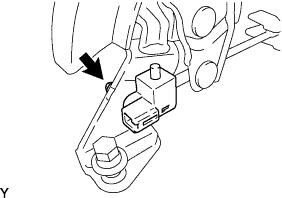
| 1. INSTALL PARKING BRAKE SWITCH |
Install the parking brake switch with the screw.
- Torque:
- 0.9 N*m{9 kgf*cm, 8 in.*lbf}
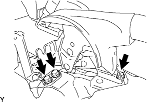
| 2. INSTALL PARKING BRAKE LEVER |
Install the parking brake pull rod and parking brake equalizer, and then provisionally install the adjusting nut and the lock nut.
Install the parking brake lever with the 3 bolts.
- Torque:
- 13 N*m{127 kgf*cm, 9 ft.*lbf}
Connect the parking brake switch connector.
| 3. INSTALL NO. 2 PARKING BRAKE CABLE ASSEMBLY |
Connect the parking brake cable to the parking brake equalizer.
| 4. INSTALL NO. 3 PARKING BRAKE CABLE ASSEMBLY |
Connect the parking brake cable to the parking brake equalizer.
| 5. INSPECT PARKING BRAKE LEVER TRAVEL |
Slowly pull the parking brake lever to the fully applied position, counting the number of clicks.
- Parking brake lever travel:
- 6 to 9 clicks at 200 N (20 kgf, 45 lbf)
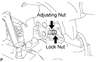
| 6. ADJUST PARKING BRAKE LEVER TRAVEL |
Loosen the lock nut and turn the adjusting nut until the parking brake lever travel is corrected to within the specified range.
- Parking brake lever travel:
- 6 to 9 clicks at 200 N (20 kgf, 45 lbf)
Tighten the lock nut.
- Torque:
- 5.4 N*m{55 kgf*cm, 48 in.*lbf}
Operate the parking brake lever 3 to 4 times, and check the parking brake lever travel.
Check whether the parking brake drags or not.
When operating the parking brake lever, check that the brake warning light illuminates.
- Standard:
- Brake warning light always illuminates at the first click.
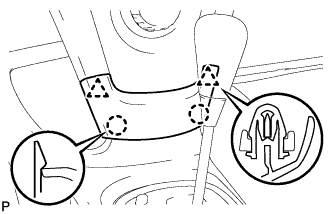
| 7. INSTALL REAR CONSOLE BOX ASSEMBLY |
Engage the 4 claws and install the rear console box.
Install the 2 bolts and 2 screws.
Connect the clamp.
| 8. INSTALL CONSOLE BOX CARPET |
Install the console box carpet.
| 9. INSTALL REAR UPPER CONSOLE PANEL SUB-ASSEMBLY |
Connect the connector.
Engage the 3 clips and 3 claws and install the rear upper console panel.
| 10. INSTALL UPPER CONSOLE PANEL SUB-ASSEMBLY |
Engage the 5 clips and the claw and install the upper console panel.
| 11. INSTALL SHIFT LEVER KNOB SUB-ASSEMBLY (for Manual Transaxle) |
| 12. INSTALL CENTER LOWER INSTRUMENT PANEL FINISH PANEL |
Engage the 2 claws and 2 clips and install the instrument panel finish panel.
| 13. CONNECT CABLE TO NEGATIVE BATTERY TERMINAL |
- Torque:
- 5.4 N*m{55 kgf*cm, 48 in.*lbf}