Front Drive Shaft Assembly (For Sedan) Installation
INSTALL FRONT DRIVE SHAFT ASSEMBLY LH
INSTALL FRONT DRIVE SHAFT ASSEMBLY RH
INSTALL AUTOMATIC TRANSMISSION CASE PROTECTOR (w/o ABS)
INSTALL FRONT AXLE ASSEMBLY
INSTALL FRONT LOWER SUSPENSION ARM
INSTALL TIE ROD END SUB-ASSEMBLY
INSTALL FRONT STABILIZER LINK ASSEMBLY
INSTALL FRONT SPEED SENSOR (w/ ABS)
INSTALL FRONT AXLE HUB NUT
INSTALL FRONT WHEEL
CONNECT CABLE TO NEGATIVE BATTERY TERMINAL
ADD AUTOMATIC TRANSAXLE FLUID (for Automatic Transaxle)
ADD MANUAL TRANSAXLE OIL (for Manual Transaxle)
INSPECT AUTOMATIC TRANSAXLE FLUID (for Automatic Transaxle)
INSPECT MANUAL TRANSAXLE OIL (for Manual Transaxle)
CHECK AUTOMATIC TRANSAXLE FLUID LEAKAGE (for Automatic Transaxle)
CHECK MANUAL TRANSAXLE OIL LEAKAGE (for Manual Transaxle)
INSPECT AND ADJUST FRONT WHEEL ALIGNMENT
CHECK ABS SENSOR SIGNAL (w/o VSC)
CHECK VSC SENSOR SIGNAL (w/ VSC)
Front Drive Shaft Assembly (For Sedan) -- Installation |
| 1. INSTALL FRONT DRIVE SHAFT ASSEMBLY LH |
for Automatic Transaxle:
Coat the spline of the inboard joint with ATF.
for Manual Transaxle:
Coat the spline of the inboard joint with gear oil.
Align the inboard joint splines and install the drive shaft with a screwdriver and hammer.
- NOTICE:
- Face the cut area of the front drive inboard joint hole snap ring downward.
- Do not damage the oil seal.
- Do not damage the inboard joint boot.
- HINT:
- Confirm whether the drive shaft is securely driven in by checking the reaction force and sound.
| 2. INSTALL FRONT DRIVE SHAFT ASSEMBLY RH |
- HINT:
- The installation procedure for the RH side is the same as that for the LH side.
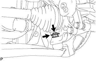
| 3. INSTALL AUTOMATIC TRANSMISSION CASE PROTECTOR (w/o ABS) |
Install the transmission case protector with the 2 bolt.
- Torque:
- 23 N*m{235 kgf*cm, 17 ft.*lbf}
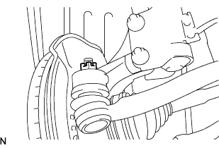
| 4. INSTALL FRONT AXLE ASSEMBLY |
Push the front axle out of the vehicle to align the spline of the drive shaft with the front axle and insert the front axle.
- NOTICE:
- Do not push the front axle further out of the vehicle than is necessary.
- Do not damage the outboard joint boot.
- Check for any foreign matter on the speed sensor rotor and insertion part.
- Do not damage the speed sensor rotor.
| 5. INSTALL FRONT LOWER SUSPENSION ARM |
Install the lower arm onto the steering knuckle with a new castle nut.
- Torque:
- 98 N*m{1,000 kgf*cm, 72 ft.*lbf}
- NOTICE:
- If the holes for the clip are not aligned, tighten the nut by a further turn of up to 60°.
Install a new clip.
| 6. INSTALL TIE ROD END SUB-ASSEMBLY |
Install the tie rod end onto the steering knuckle with a new castle nut.
- Torque:
- 49 N*m{500 kgf*cm, 36 ft.*lbf}
- NOTICE:
- If the holes for the clip are not aligned, tighten the nut by a further turn of up to 60°.
Install a new cotter pin.
| 7. INSTALL FRONT STABILIZER LINK ASSEMBLY |
Install the stabilizer link with the nut.
- Torque:
- 74 N*m{755 kgf*cm, 55 ft.*lbf}
- HINT:
- If the ball joint turns together with the nut, use a socket hexagon wrench 6 to hold the stud.
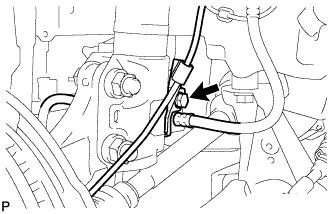
| 8. INSTALL FRONT SPEED SENSOR (w/ ABS) |
Install the speed sensor onto the steering knuckle with the bolt.
- Torque:
- 8.5 N*m{87 kgf*cm, 75 in.*lbf}
- NOTICE:
- Check that the speed sensor tip and installation portion are free of foreign matter.
- Install the speed sensor without turning it from its original installation angle.
Install the flexible hose and speed sensor with the bolt.
- Torque:
- 29 N*m{300 kgf*cm, 22 ft.*lbf}
- NOTICE:
- Install the flexible hose and speed sensor without twisting them.
| 9. INSTALL FRONT AXLE HUB NUT |
Using a 30 mm socket wrench, install a new axle hub nut.
- Torque:
- 216 N*m{2,203 kgf*cm, 160 ft.*lbf}
Using a chisel and hammer, caulk the axle hub nut.
- Torque:
- 103 N*m{1,050 kgf*cm, 76 ft.*lbf}
| 11. CONNECT CABLE TO NEGATIVE BATTERY TERMINAL |
- Torque:
- 5.4 N*m{55 kgf*cm, 48 in.*lbf}
| 12. ADD AUTOMATIC TRANSAXLE FLUID (for Automatic Transaxle) |
Automatic Transaxle FluidClassification
| Capacity (Reference)
|
Toyota Genuine ATF WS or equivalent
| Dry fill
| 6.4 liters (6.8 US qts, 5.6 Imp. qts)
|
Drain and refill
| 2.5 liters (2.6 US qts, 2.2 Imp. qts)
|
| 13. ADD MANUAL TRANSAXLE OIL (for Manual Transaxle) |
| 14. INSPECT AUTOMATIC TRANSAXLE FLUID (for Automatic Transaxle) |
- HINT:
- Drive the vehicle until the engine and transaxle are at normal operating temperature.
- Fluid temperature:
- 70 to 80 °C (158 to 176 °F)
Park the vehicle on a level surface and engage the parking brake.
With the engine idling and the brake pedal depressed, shift the shift lever into all positions from P to L, and then return it to the P position.
Pull out the oil level gauge and wipe it clean.
Push it fully back into the pipe.
Pull it out and check that the fluid level is within the HOT range.
If there is any leakage, repair or replace O-rings, FIPGs, oil seals, plugs or other parts.
| 15. INSPECT MANUAL TRANSAXLE OIL (for Manual Transaxle) |
Text in Illustration*a
| 0 to 5 mm (0 to 0.196 in.)
|
Stop the vehicle in a level place.
Remove the transmission filler plug and the gasket.
Check that the oil surface is within 5 mm (0.20 in.) of the bottom of the transmission filler plug opening.
- NOTICE:
- Excessively large or small amounts of oil may cause problems.
- After replacing the oil, drive the vehicle and check the oil level again.
Check for oil leakage when the oil level is low.
Install the transmission filler plug and a new gasket.
- Torque:
- 39 N*m{400 kgf*cm, 29 ft.*lbf}
| 16. CHECK AUTOMATIC TRANSAXLE FLUID LEAKAGE (for Automatic Transaxle) |
| 17. CHECK MANUAL TRANSAXLE OIL LEAKAGE (for Manual Transaxle) |
| 18. INSPECT AND ADJUST FRONT WHEEL ALIGNMENT |
(YARIS_NCP93 RM000001BCN01PX.html)
| 19. CHECK ABS SENSOR SIGNAL (w/o VSC) |
(YARIS_NCP93 RM000000XHT08HX.html)
| 20. CHECK VSC SENSOR SIGNAL (w/ VSC) |
(YARIS_NCP93 RM000000XHT08IX.html)