Output Shaft (For Hatchback) Inspection
INSPECT OUTPUT SHAFT
INSPECT 2ND GEAR
INSPECT 1ST GEAR
INSPECT 1ST GEAR THRUST WASHER
INSPECT NO. 1 SYNCHRONIZER RING (FOR 2ND GEAR)
INSPECT NO. 1 SYNCHRONIZER RING (FOR 1ST GEAR)
INSPECT REVERSE GEAR
Output Shaft (For Hatchback) -- Inspection |
Using a dial indicator and 2 V-blocks, check the output shaft runout.
- Maximum runout:
- 0.015 mm (0.000591 in.)
If the runout exceeds the maximum, replace the output shaft.
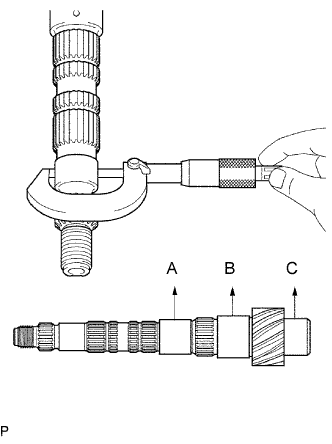
Using a micrometer, measure the outer diameter of the output shaft journal surface, at the locations indicated.
- Standard outer diameter:
- Part A:
- 31.985 to 32.000 mm (1.2592 to 1.2598 in.)
- Part B:
- 37.985 to 38.000 mm (1.495 to 1.496 in.)
- Part C:
- 32.985 to 33.000 mm (1.2986 to 1.2992 in.)
If either outer diameters are less than the minimums, replace the output shaft.
Using a cylinder gauge, measure the inside diameter of the 2nd gear.
- Standard inside diameter:
- 38.015 to 38.031 mm (1.4967 to 1.4973 in.)
- Maximum inside diameter:
- 38.031 mm (1.4973 in.)
If the inside diameter exceeds the maximum, replace the 2nd gear.
Using a cylinder gauge, measure the inside diameter of the 1st gear.
- Standard inside diameter:
- 44.015 to 44.031 mm (1.7333 to 1.7334 in.)
- Maximum inside diameter:
- 44.031 mm (1.7334 in.)
If the inside diameter exceeds the maximum, replace the 1st gear.
| 4. INSPECT 1ST GEAR THRUST WASHER |
Using a micrometer, measure the 1st gear thrust washer.
- Standard thickness:
- 5.975 to 6.025 mm (0.235 to 0.237 in.)
- Minimum thickness:
- 5.975 mm (0.235 in.)
If the thickness is less than the minimum, replace the 1st gear thrust washer.
| 5. INSPECT NO. 1 SYNCHRONIZER RING (FOR 2ND GEAR) |
Check the No. 1 synchronizer ring for wear and damage.
Coat the 2nd gear cone with gear oil.
Turn the No. 1 synchronizer ring in one direction while pushing it against the 2nd gear cone.
Check that the No. 1 synchronizer ring locks.
If the No. 1 synchronizer ring does not lock, replace the No. 1 synchronizer ring.
Using a feeler gauge, measure the clearance between the No. 1 synchronizer ring back and the gear spline end.
- Standard clearance:
- 0.7 to 1.3 mm (0.0276 to 0.0512 in.)
- Minimum clearance:
- 0.7 mm (0.0276 in.)
If the clearance is less than the minimum, replace the No. 1 synchronizer ring.
| 6. INSPECT NO. 1 SYNCHRONIZER RING (FOR 1ST GEAR) |
Check the No. 1 synchronizer ring for wear and damage.
Coat the 1st gear cone with gear oil.
Turn the No. 1 synchronizer ring in one direction while pushing it against the 1st gear cone.
Check that the No. 1 synchronizer ring locks.
If the No. 1 synchronizer ring does not lock, replace the No. 1 synchronizer ring.
Using a feeler gauge, measure the clearance between the No. 1 synchronizer ring back and the gear spline end.
- Standard clearance:
- 0.75 to 1.7 mm (0.0295 to 0.0650 in.)
- Minimum clearance:
- 0.60 mm (0.0295 in.)
If the clearance is less than the minimum, replace the No. 1 synchronizer ring.
Check that the No. 1 transmission clutch hub and the reverse gear slide smoothly.
Check that the edges of the reverse gear spline gear are not worn down.
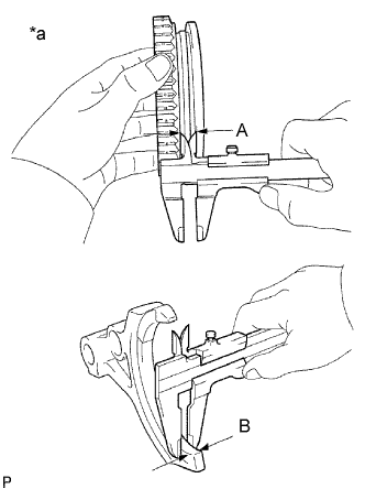
Using a vernier caliper, measure the width of the reverse gear groove (A) and the thickness of the claw part on the reverse shift fork (B), and calculate the clearance.
Text in Illustration*a
| Clearance = (A - B)
|
- Standard clearance (A - B):
- 0.15 to 0.35 mm (0.00591 to 0.0138 in.)
If the clearance is outside the specifications, replace the reverse gear and reverse shift fork.