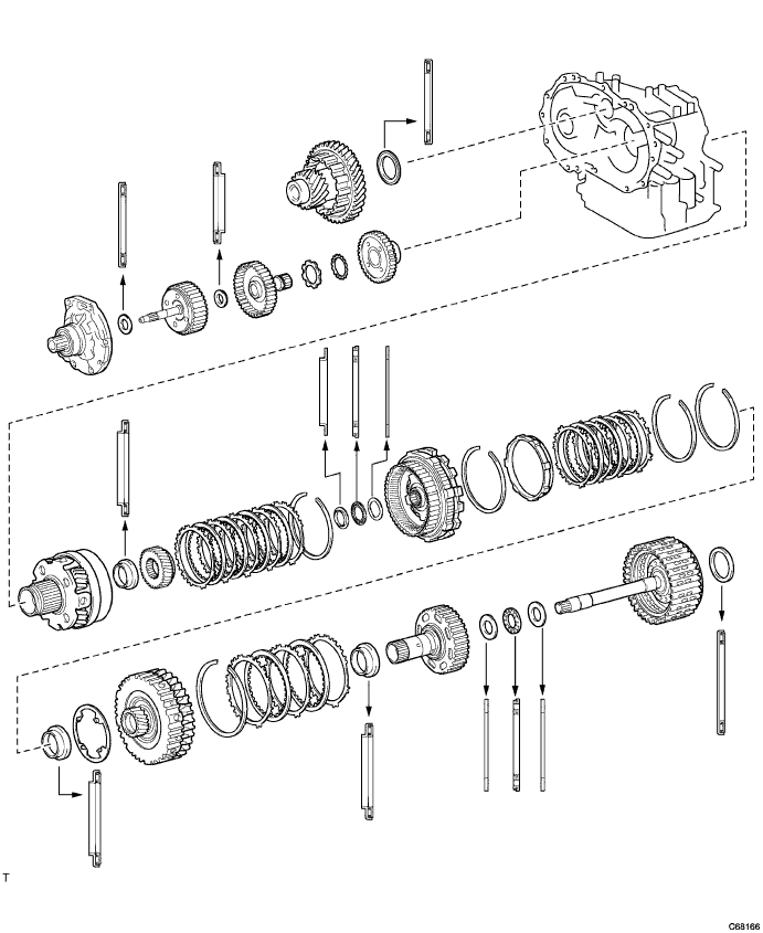
Automatic Transaxle Unit (For Sedan) Reassembly
BEARING POSITION
INSPECT DIFFERENTIAL CASE TAPERED ROLLER BEARING PRELOAD
INSTALL TRANSAXLE CASE OIL SEAL
INSTALL FRONT TRANSAXLE CASE OIL SEAL
INSTALL FRONT DRIVE PINION REAR TAPERED ROLLER BEARING
INSTALL FRONT DRIVE PINION FRONT TAPERED ROLLER BEARING
INSTALL DIFFERENTIAL GEAR LUBE APPLY TUBE
INSTALL BEARING LOCK PLATE
INSTALL COUNTER DRIVE GEAR HOLE SNAP RING
INSTALL COUNTER DRIVE GEAR BEARING
INSTALL MANUAL VALVE LEVER SHAFT OIL SEAL
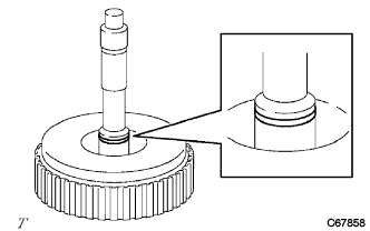
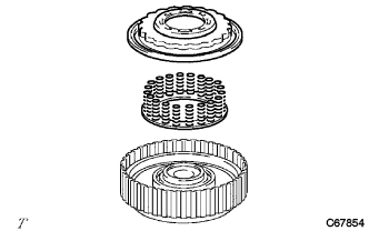
INSTALL DIFFERENTIAL DRIVE PINION
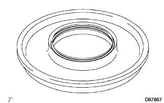
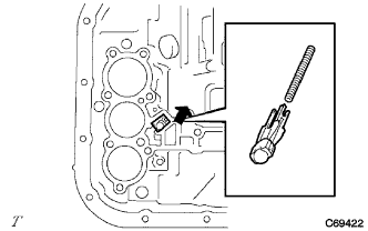
INSTALL DIFFERENTIAL DRIVE PINION PLUG
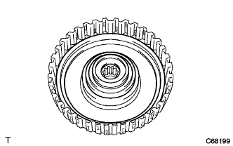
INSTALL COUNTER DRIVEN GEAR
INSTALL PARKING LOCK PAWL
INSTALL MANUAL VALVE LEVER SHAFT
INSTALL PARKING LOCK ROD SUB-ASSEMBLY
INSTALL MANUAL VALVE LEVER SUB-ASSEMBLY
INSTALL MANUAL VALVE LEVER SHAFT RETAINER SPRING
INSTALL PARKING LOCK PAWL BRACKET
INSTALL NO. 2 1ST AND REVERSE BRAKE PISTON O-RING
INSTALL NO. 2 1ST AND REVERSE BRAKE PISTON
INSTALL 1ST AND REVERSE BRAKE RETURN SPRING SUB-ASSEMBLY
INSTALL COUNTER DRIVE GEAR
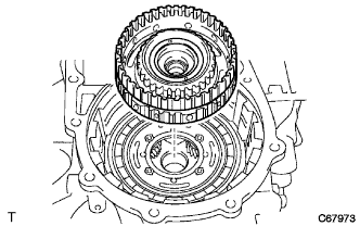
INSTALL PLANETARY GEAR ASSEMBLY
INSTALL COUNTER DRIVE GEAR NUT
INSTALL 1ST AND REVERSE BRAKE DISC
INSPECT PACK CLEARANCE OF FIRST AND REVERSE BRAKE
INSTALL FRONT PLANETARY SUN GEAR
INSTALL 2ND BRAKE CYLINDER O-RING
INSTALL 2ND BRAKE PISTON
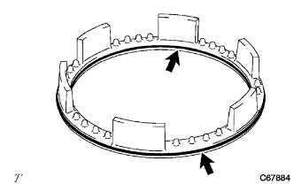
INSTALL 2ND BRAKE PISTON RETURN SPRING SUB-ASSEMBLY
INSTALL OUTER RACE RETAINER
INSTALL NO. 2 1-WAY CLUTCH
INSTALL REAR PLANETARY GEAR THRUST NEEDLE ROLLER BEARING
INSTALL REAR PLANETARY GEAR ASSEMBLY
INSPECT NO. 2 1-WAY CLUTCH
INSTALL 2ND BRAKE PISTON SLEEVE
INSTALL 2ND BRAKE BRAKE DISC
INSPECT PACK CLEARANCE OF 2ND BRAKE
INSTALL 2ND COAST AND OVERDRIVE BRAKE FLANGE HOLE SNAP RING
INSTALL 1-WAY CLUTCH ASSEMBLY
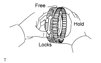
INSPECT 1-WAY CLUTCH ASSEMBLY
INSTALL REAR PLANETARY SUN GEAR THRUST NEEDLE ROLLER BEARING
INSTALL REAR PLANETARY SUN GEAR ASSEMBLY
INSTALL REAR NO. 2 PLANETARY SUN GEAR THRUST NEEDLE ROLLER BEARING
INSTALL DIRECT CLUTCH HUB
INSTALL THRUST NEEDLE ROLLER BEARING
INSTALL 2ND COAST AND OVERDRIVE BRAKE DISC
INSTALL DIRECT CLUTCH DRUM O-RING
INSTALL DIRECT CLUTCH PISTON O-RING
INSTALL DIRECT CLUTCH DRUM SUB-ASSEMBLY
INSTALL DIRECT CLUTCH PISTON SUB-ASSEMBLY
INSTALL DIRECT CLUTCH RETURN SPRING SUB-ASSEMBLY
INSTALL DIRECT CLUTCH DISK
INSTALL REVERSE CLUTCH DISC
INSPECT PACK CLEARANCE OF REVERSE CLUTCH
INSPECT PACK CLEARANCE OF DIRECT CLUTCH
INSTALL INTERMEDIATE SHAFT ASSEMBLY
INSPECT 2ND COAST AND OVERDRIVE BRAKE CLEARANCE
INSTALL REAR CLUTCH DRUM THRUST NEEDLE ROLLER BEARING
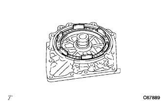
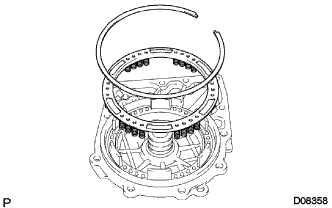
INSPECT INTERMEDIATE SHAFT ASSEMBLY
INSTALL TRANSAXLE CASE GASKET
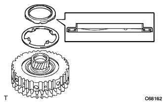
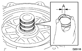
INSTALL REAR TRANSAXLE COVER NEEDLE ROLLER BEARING
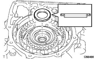
INSTALL CLUTCH DRUM OIL SEAL RING
INSTALL 2ND COAST AND OVERDRIVE O-RING
INSTALL 2ND COAST AND OVERDRIVE BRAKE PISTON
INSTALL OVERDRIVE BRAKE RETURN SPRING SUB-ASSEMBLY
INSTALL REAR TRANSAXLE COVER PLUG
INSTALL REAR TRANSAXLE COVER ASSEMBLY
INSTALL FORWARD CLUTCH HUB SUB-ASSEMBLY
INSTALL FORWARD CLUTCH HUB THRUST NEEDLE ROLLER BEARING
INSTALL INPUT SHAFT OIL SEAL RING
INSTALL FORWARD CLUTCH PISTON O-RING
INSTALL FORWARD CLUTCH PISTON
INSTALL FORWARD CLUTCH RETURN SPRING SUB-ASSEMBLY
INSTALL FRONT CLUTCH CLUTCH DISC
INSPECT PACK CLEARANCE OF FORWARD CLUTCH
INSTALL STATOR SHAFT THRUST NEEDLE ROLLER BEARING
INSTALL INPUT SHAFT ASSEMBLY
INSTALL OVERDRIVE BRAKE GASKET
INSTALL DIFFERENTIAL GEAR ASSEMBLY
INSTALL OIL PUMP ASSEMBLY
INSPECT INPUT SHAFT ASSEMBLY
INSPECT INPUT SHAFT END PLAY
INSTALL TRANSAXLE HOUSING
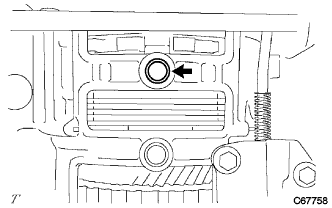
INSTALL C-2 ACCUMULATOR PISTON
INSTALL C-3 ACCUMULATOR PISTON
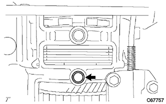
INSTALL B-2 ACCUMULATOR PISTON
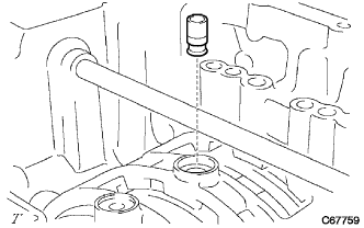
INSTALL CHECK BALL BODY
INSTALL BRAKE DRUM GASKET
INSTALL TRANSAXLE CASE GASKET
INSTALL TRANSAXLE CASE 2ND BRAKE GASKET
INSTALL TRANSMISSION WIRE
INSTALL TRANSMISSION VALVE BODY ASSEMBLY
INSTALL VALVE BODY OIL STRAINER ASSEMBLY
INSTALL AUTOMATIC TRANSAXLE OIL PAN SUB-ASSEMBLY
INSTALL BREATHER PLUG HOSE
INSTALL NO. 1 TRANSAXLE CASE PLUG
INSTALL OIL COOLER TUBE UNION
INSTALL TRANSMISSION REVOLUTION SENSOR
INSTALL PARK/NEUTRAL POSITION SWITCH ASSEMBLY
INSTALL SPEEDOMETER DRIVEN GEAR
INSTALL SPEEDOMETER SENSOR
Automatic Transaxle Unit (For Sedan) -- Reassembly |
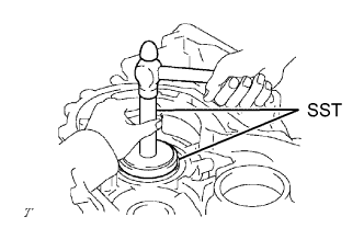
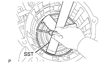
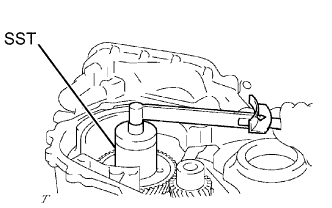
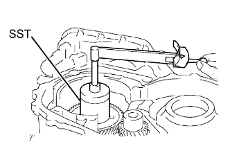
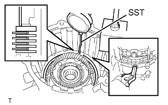
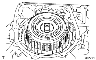
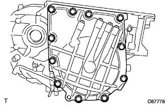
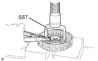
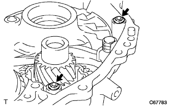
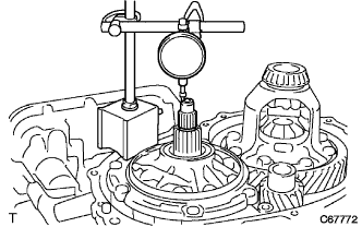
| 2. INSPECT DIFFERENTIAL CASE TAPERED ROLLER BEARING PRELOAD |
Coat the front differential case and bearing with Toyota Genuine ATF WS or equivalent and install them onto the transaxle case.
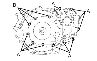
Install the transaxle housing with the 14 bolts.
- Torque:
- Bolt A:
- 29 N*m{300 kgf*cm, 22 ft.*lbf}
- Bolt B:
- 22 N*m{225 kgf*cm, 16 ft.*lbf}
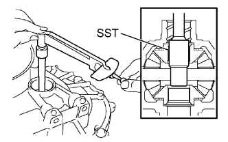
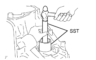
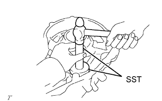
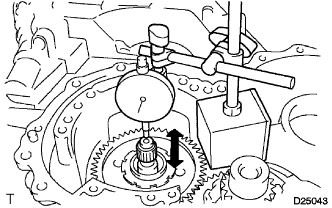
Using SST and a small torque wrench, measure the preload of the differential gear.
- SST
- 09564-32011
- Preload:
Bearing
| Standard
|
New
| 0.98 to 1.57 N*m (10.0 to 16.0 kgf*cm 8.7 to 13.9 in.*lbf)
|
Used
| 0.49 to 0.78 N*m (5.0 to 8.0 kgf*cm 4.3 to 6.9 in.*lbf)
|
If the preload is not within the specifications, remove the differential from the transaxle case.
Select a new transaxle case side adjusting shim in accordance with the following table.
- Adjusting Shim Thickness:
Mark
| Thickness mm (in.)
| Mark
| Thickness mm (in.)
|
01
| 1.90 (0.0748)
| 11
| 2.40 (0.0945)
|
02
| 1.95 (0.0768)
| 12
| 2.45 (0.0965)
|
03
| 2.00 (0.0787)
| 13
| 2.50 (0.0984)
|
04
| 2.05 (0.0807)
| 14
| 2.55 (0.1004)
|
05
| 2.10 (0.0827)
| 15
| 2.60 (0.1024)
|
06
| 2.15 (0.0846)
| 16
| 2.65 (0.1043)
|
07
| 2.20 (0.0866)
| 17
| 2.70 (0.1063)
|
08
| 2.25 (0.0885)
| 18
| 2.75 (0.1082)
|
09
| 2.30 (0.0906)
| 19
| 2.80 (0.1102)
|
10
| 2.35 (0.0925)
| -
| -
|
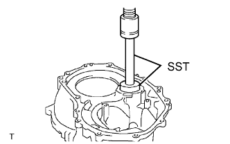
| 3. INSTALL TRANSAXLE CASE OIL SEAL |
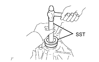
Coat the lip of a new oil seal with MP grease.
Using SST and a hammer, drive in a new oil seal.
- SST
- 09554-14010
09950-70010(09951-07100)
- Oil seal drive in depth:
- 1.5 to 2.5 mm (0.059 to 0.098 in.)
| 4. INSTALL FRONT TRANSAXLE CASE OIL SEAL |
Coat the lip of a new oil seal with MP grease.
Using SST and a hammer, drive in a new oil seal.
- SST
- 09726-27012(09726-02041)
09950-70010(09951-07150)
- Oil seal drive in depth:
- 5.4 to 6.4 mm (0.213 to 0.252 in.)
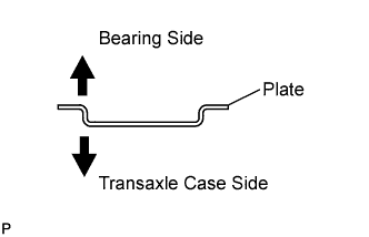
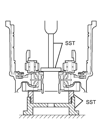
| 5. INSTALL FRONT DRIVE PINION REAR TAPERED ROLLER BEARING |
Install transaxle case plate No. 1 onto the transaxle case.
Using SST and a hammer, install the front drive pinion rear tapered roller bearing onto the transaxle case.
- SST
- 09950-60010(09951-00610)
09950-70010(09951-07150)
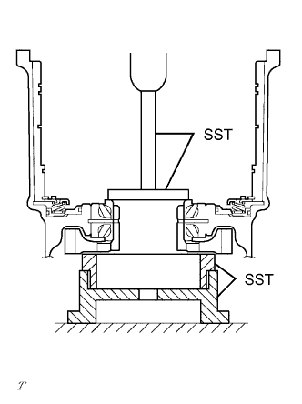
| 6. INSTALL FRONT DRIVE PINION FRONT TAPERED ROLLER BEARING |
Install the thrust bearing onto the transaxle housing.
Using SST and a press, install a new front drive pinion front tapered roller bearing onto the transaxle housing.
- SST
- 09950-60010(09951-00650)
09950-70010(09951-07150)
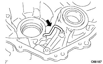
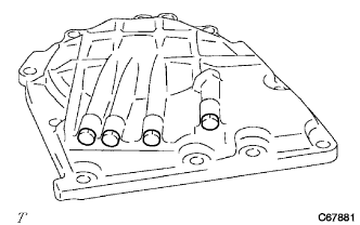
| 7. INSTALL DIFFERENTIAL GEAR LUBE APPLY TUBE |
Install the differential gear lube apply tube onto the transaxle housing.
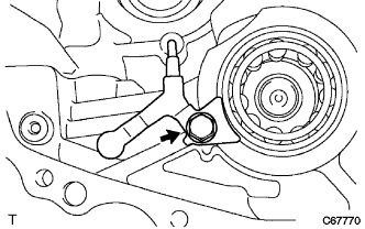
| 8. INSTALL BEARING LOCK PLATE |
Install the bearing lock plate onto the transaxle housing with the bolt.
- Torque:
- 11 N*m{115 kgf*cm, 8 ft.*lbf}
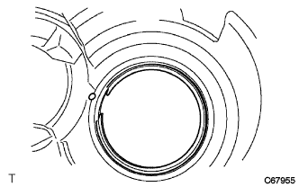
| 9. INSTALL COUNTER DRIVE GEAR HOLE SNAP RING |
Using a screwdriver, install the counter drive gear hole snap ring onto the transaxle case.
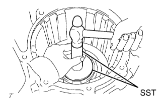
| 10. INSTALL COUNTER DRIVE GEAR BEARING |
Using SST and a hammer, install the counter drive gear bearing LH outer race onto the transaxle case.
- SST
- 09950-60020(09951-00890)
09950-70010(09951-07150)
Using SST and a hammer, install the counter drive gear bearing RH outer race onto the transaxle case.
- SST
- 09950-60020(09951-00890)
09950-70010(09951-07150)
Install the counter drive gear bearing onto the transaxle case.
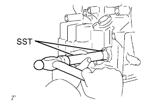
| 11. INSTALL MANUAL VALVE LEVER SHAFT OIL SEAL |
Coat the lip of a new oil seal with MP grease.
Using SST and a hammer, install a new manual valve lever shaft oil seal.
- SST
- 09950-60010(09951-00220)
09950-70010(09951-07100)
- Oil seal drive in depth:
- -0.5 to 0.5 mm (-0.020 to 0.020 in.)
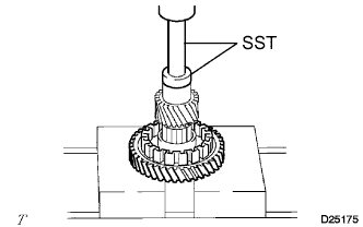
| 12. INSTALL DIFFERENTIAL DRIVE PINION |
Using SST and a press, install the differential drive pinion onto the counter driven gear.
- SST
- 09950-60010(09951-00350)
09950-70010(09951-07150)
- NOTICE:
- When replacing the counter driven gear, replace the counter drive gear in the transaxle case as well.
- Press the differential drive pinion in until it comes into contact with the counter driven gear.
| 13. INSTALL DIFFERENTIAL DRIVE PINION PLUG |
Using SST and a plastic hammer, install a new differential drive pinion plug onto the differential drive pinion.
- SST
- 09221-25026(09221-00071)
- Standard clearance:
- 2.5 to 2.6 mm (0.0984 to 0.1023 in.)
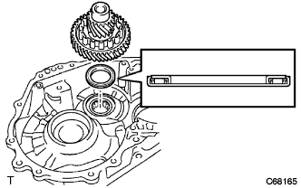
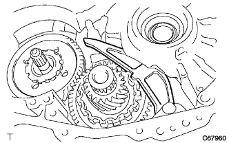
| 14. INSTALL COUNTER DRIVEN GEAR |
Install the counter driven gear and drive pinion thrust bearing onto the transaxle case.
| 15. INSTALL PARKING LOCK PAWL |
Coat the parking lock pawl shaft with Toyota Genuine ATF WS or equivalent.
Install the parking lock pawl, parking lock pawl shaft torsion spring and parking lock pawl shaft onto the transaxle case.
- NOTICE:
- Check that the parking lock pawl moves smoothly.
| 16. INSTALL MANUAL VALVE LEVER SHAFT |
Install the manual valve lever shaft onto the transaxle case.
- NOTICE:
- Do not damage the oil seal lip.
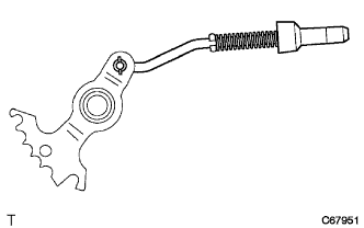
| 17. INSTALL PARKING LOCK ROD SUB-ASSEMBLY |
Install the parking lock rod onto the manual valve lever.
| 18. INSTALL MANUAL VALVE LEVER SUB-ASSEMBLY |
Coat the manual valve lever sub-assembly with Toyota Genuine ATF WS or equivalent.
Install the manual valve lever and a new manual valve lever spacer onto the manual valve lever shaft.
Using a pin punch and hammer, drive in the pin.
Turn the spacer and lever shaft to align the small hole for locating the staking position in the spacer with the staking position mark on the lever shaft.
Using a pin punch, stake the spacer through the small hole.
Check that the spacer does not turn.
| 19. INSTALL MANUAL VALVE LEVER SHAFT RETAINER SPRING |
Install the manual valve lever shaft retainer spring onto the manual valve lever shaft.
| 20. INSTALL PARKING LOCK PAWL BRACKET |
Install the parking lock pawl bracket, parking lock rod and cam guide sleeve onto the transaxle case with the 3 bolts.
- Torque:
- 20 N*m{205 kgf*cm, 15 ft.*lbf}
| 21. INSTALL NO. 2 1ST AND REVERSE BRAKE PISTON O-RING |
Coat 2 new O-rings with Toyota Genuine ATF WS or equivalent, and install them onto No. 2 brake piston.
| 22. INSTALL NO. 2 1ST AND REVERSE BRAKE PISTON |
Coat No. 2 1st and reverse brake piston with Toyota Genuine ATF WS or equivalent, and install it into the transaxle case.
- NOTICE:
- Do not damage the oil seal lip.
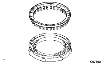
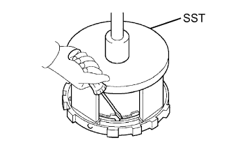
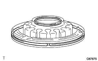
| 23. INSTALL 1ST AND REVERSE BRAKE RETURN SPRING SUB-ASSEMBLY |
Install the 1st and reverse brake return spring sub-assembly onto the transaxle case.
Using SST, a press and a screwdriver, install the snap ring.
- SST
- 09387-00070
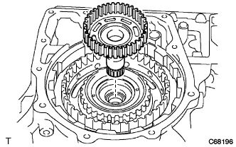
| 24. INSTALL COUNTER DRIVE GEAR |
Using SST and a press, install the counter drive gear onto the transaxle case.
- SST
- 09223-15030
09527-17011
09950-60010(09951-00650)
09950-70010(09951-07150)
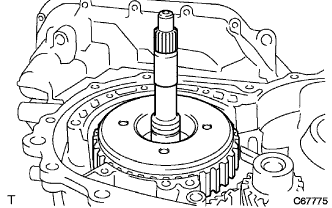
| 25. INSTALL PLANETARY GEAR ASSEMBLY |
Using SST and a press, install the planetary gear assembly onto the transaxle case.
- SST
- 09950-60010(09951-00480)
09223-15030
09527-17011
09950-70010(09951-07150)
| 26. INSTALL COUNTER DRIVE GEAR NUT |
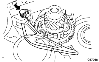
Fix the counter driven gear with the parking lock pawl.
Using SST, install a new lock washer and nut.
- SST
- 09387-00121
- Torque:
- 280 N*m{2,855 kgf*cm, 207 ft.*lbf}
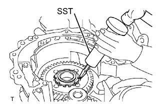
Using SST and a small torque wrench, measure the rotating torque while turning the counter drive gear at 60 turns per minute.
- SST
- 09387-00121
- Rotating torque:
- 0.20 to 0.49 N*m (2 to 5 kgf*cm, 2 to 4 in.*lbf)
Using SST and a hammer, stake the lock nut washer.
- SST
- 09930-00010
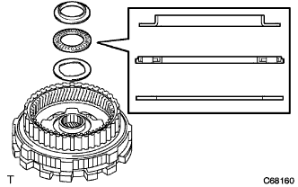
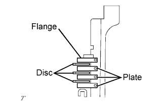
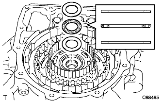
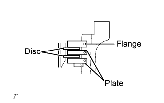
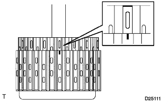
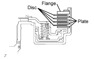
| 27. INSTALL 1ST AND REVERSE BRAKE DISC |
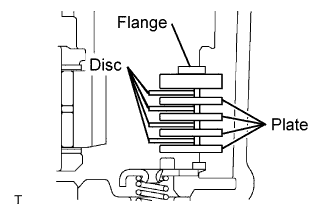
Install the 4 plates, 4 discs and flange onto the transaxle case.
Using a screwdriver, install the snap ring.
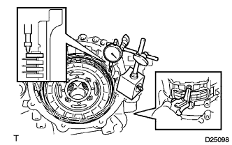
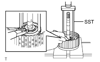
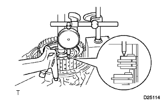
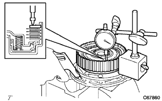
| 28. INSPECT PACK CLEARANCE OF FIRST AND REVERSE BRAKE |
Using SST and a dial indicator, measure the first and reverse brake clearance while pressing the disc and plate from the rear side.
- SST
- 09350-36010(09350-06110)
- Pack clearance:
- 0.806 to 1.206 mm (0.0317 to 0.0475 in.)
- NOTICE:
- If the clearance is outside the specifications, select a new brake flange.
- HINT:
- There are 4 different flange thicknesses.
- Flange thickness:
Mark
| Thickness mm (in.)
| Mark
| Thickness mm (in.)
|
-
| 3.4 (0.134)
| 2
| 3.8 (0.150)
|
1
| 3.6 (0.142)
| 3
| 4.0 (0.157)
|
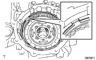
Check that the 1st and reverse brake piston moves when compressed air is applied (392 kPa, 4.0 kgf/cm2, 57 psi) to the oil hole.
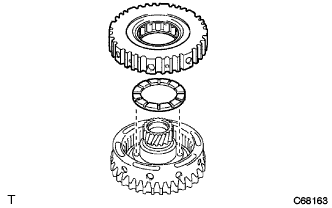
| 29. INSTALL FRONT PLANETARY SUN GEAR |
Install the planetary sun gear and needle roller bearing onto the planetary gear assembly.
| 30. INSTALL 2ND BRAKE CYLINDER O-RING |
Coat 2 new 2nd brake cylinder O-rings with Toyota Genuine ATF WS or equivalent, and install them into the 2nd brake cylinder.
- NOTICE:
- Do not damage the O-rings.
| 31. INSTALL 2ND BRAKE PISTON |
Coat the 2nd brake piston with Toyota Genuine ATF WS or equivalent, and install it into the 2nd brake cylinder.
- CAUTION:
- Do not damage the O-rings when pressing the 2nd brake piston into the 2nd brake cylinder by hand.
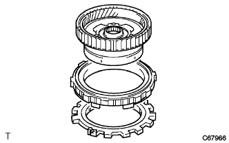
| 32. INSTALL 2ND BRAKE PISTON RETURN SPRING SUB-ASSEMBLY |
Install the piston return spring.
Place SST on the piston return spring, and compress the piston return spring with a press.
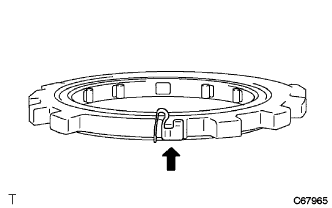
Using a screwdriver, install the snap ring.
- NOTICE:
- Make sure that the end gap of the snap ring is not aligned with the piston return spring claw.
| 33. INSTALL OUTER RACE RETAINER |
Install the outer retainer onto No. 2 1-way clutch.
| 34. INSTALL NO. 2 1-WAY CLUTCH |
Install the 1-way clutch and 2nd brake piston assembly onto the rear planetary gear assembly.
| 35. INSTALL REAR PLANETARY GEAR THRUST NEEDLE ROLLER BEARING |
Install No. 2 thrust bearing race, the planetary gear thrust needle roller bearing and thrust bearing race onto the rear planetary gear assembly.
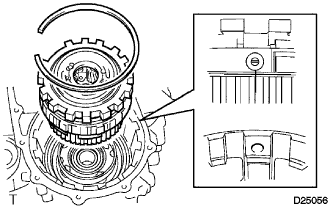
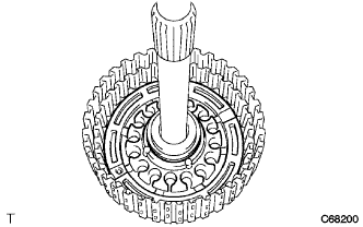
| 36. INSTALL REAR PLANETARY GEAR ASSEMBLY |
Install the rear planetary gear assembly onto the transaxle case.
Using a screwdriver, install the snap ring.
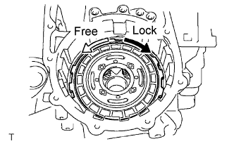
| 37. INSPECT NO. 2 1-WAY CLUTCH |
Check that the rear planetary gear turns freely counterclockwise and locks when turned clockwise.
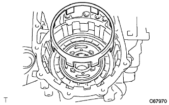
| 38. INSTALL 2ND BRAKE PISTON SLEEVE |
Install the 2nd brake piston sleeve onto the transaxle case.
| 39. INSTALL 2ND BRAKE BRAKE DISC |
Install the 3 discs, 3 plates and flange onto the transaxle case.
Using a screwdriver, install a snap ring onto the transaxle case.
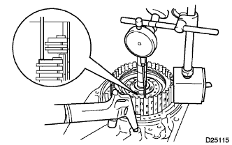
| 40. INSPECT PACK CLEARANCE OF 2ND BRAKE |
Using a dial indicator, measure the 2nd brake pack clearance while applying and releasing compressed air (392 to 785 kPa, 4 to 8 kgf/cm2, 57 to 114 psi).
- Pack clearance:
- 0.847 to 1.247 mm (0.0333 to 0.0491 in.)
- NOTICE:
- If the clearance is outside the specifications, select a new brake flange.
- HINT:
- There are 4 different flange thicknesses.
- Flange thickness:
Mark
| Thickness mm (in.)
| Mark
| Thickness mm (in.)
|
-
| 3.0 (0.118)
| 2
| 3.4 (0.134)
|
1
| 3.2 (0.126)
| 3
| 3.6 (0.142)
|
| 41. INSTALL 2ND COAST AND OVERDRIVE BRAKE FLANGE HOLE SNAP RING |
Using a screwdriver, install a snap ring onto the transaxle case.
| 42. INSTALL 1-WAY CLUTCH ASSEMBLY |
Install No. 2 thrust washer onto the rear planetary gear assembly.
Install 1-way clutch assembly onto the rear planetary sun gear assembly.
| 43. INSPECT 1-WAY CLUTCH ASSEMBLY |
Hold the rear planetary sun gear and turn the 1-way clutch and check that the 1-way clutch turns freely counterclockwise and locks when turned clockwise.
| 44. INSTALL REAR PLANETARY SUN GEAR THRUST NEEDLE ROLLER BEARING |
Install the thrust bearing and a washer onto the rear planetary sun gear.
| 45. INSTALL REAR PLANETARY SUN GEAR ASSEMBLY |
Install the rear planetary sun gear assembly.
| 46. INSTALL REAR NO. 2 PLANETARY SUN GEAR THRUST NEEDLE ROLLER BEARING |
Install the thrust bearing onto the rear planetary sun gear.
| 47. INSTALL DIRECT CLUTCH HUB |
Install the direct clutch hub.
| 48. INSTALL THRUST NEEDLE ROLLER BEARING |
Install No. 3 thrust bearing race, the thrust needle roller bearing and the C-2 hub thrust bearing race onto the direct clutch hub.
| 49. INSTALL 2ND COAST AND OVERDRIVE BRAKE DISC |
Install the 2 discs, 2 plates and flange onto the transaxle case.
| 50. INSTALL DIRECT CLUTCH DRUM O-RING |
Coat a new O-ring with Toyota Genuine ATF WS or equivalent and install it into the direct clutch drum.
- NOTICE:
- Do not damage the O-rings.
| 51. INSTALL DIRECT CLUTCH PISTON O-RING |
Coat 2 new O-rings with Toyota Genuine ATF WS or equivalent and install them into the direct clutch piston.
- NOTICE:
- Do not damage the O-rings.
| 52. INSTALL DIRECT CLUTCH DRUM SUB-ASSEMBLY |
Coat the direct clutch drum with Toyota Genuine ATF WS or equivalent.
Align the cutout in the intermediate shaft assembly with the matchmark on the direct clutch drum and install the direct clutch drum onto the intermediate shaft assembly.
- NOTICE:
- Do not damage the O-ring or the lip of the clutch drum.
| 53. INSTALL DIRECT CLUTCH PISTON SUB-ASSEMBLY |
Coat the direct clutch piston with Toyota Genuine ATF WS or equivalent and install it into the intermediate shaft.
- NOTICE:
- Do not damage the O-ring or the direct clutch piston.
| 54. INSTALL DIRECT CLUTCH RETURN SPRING SUB-ASSEMBLY |
Install the direct clutch return spring onto the direct clutch piston.
Place SST on the piston return spring and compress the springs with a press.
- SST
- 09387-00020
Using snap ring pliers, install the snap ring into the direct clutch drum.
- NOTICE:
- Stop pressing the press when the spring seat is lowered to 1 to 2 mm (0.039 to 0.078 in.) from the snap ring groove to prevent the spring seat from deforming.
- Do not expand the snap ring excessively.
| 55. INSTALL DIRECT CLUTCH DISK |
Coat the 3 rear clutch flanges, 3 discs and direct clutch flange with Toyota Genuine ATF WS or equivalent and install them onto the intermediate shaft.
Install the snap ring into the intermediate shaft.
| 56. INSTALL REVERSE CLUTCH DISC |
Coat the 2 plates, 2 discs and flange with Toyota Genuine ATF WS or equivalent, and install them onto the intermediate shaft.
Install the snap ring into the intermediate shaft.
| 57. INSPECT PACK CLEARANCE OF REVERSE CLUTCH |
Install the intermediate shaft and thrust needle roller bearing onto the transaxle rear cover.
Using a dial indicator, measure the reverse clutch pack clearance while applying and releasing compressed air (392 kPa, 4.0 kgf/cm2, 57 psi).
- Pack clearance:
- 0.86 to 1.26 mm (0.0339 to 0.0496 in.)
- NOTICE:
- If the clearance is outside the specifications, select a new brake flange.
- HINT:
- There are 4 different flange thicknesses.
Flange thicknessNo.
| Thickness mm (in.)
| No.
| Thickness mm (in.)
|
-
| 3.0
(0.118)
| 2
| 3.4
(0.134)
|
1
| 3.2
(0.126)
| 3
| 3.6
(0.142)
|
| 58. INSPECT PACK CLEARANCE OF DIRECT CLUTCH |
Install the intermediate shaft and thrust needle roller bearing onto the transaxle rear cover.
Using a dial indicator and measuring terminal (SST), measure the forward clutch pack clearance while applying and releasing compressed air (392 kPa, 4.0 kgf/cm2, 57 psi).
- SST
- 09350-36010(09350-06110)
- HINT:
- The direct and reverse clutch will come out as the compressed air is applied. Therefore, while performing the check, press on the input shaft of the direct and reverse clutch using a stamping machine or the equivalent so that the pressure is not applied to the direct and reverse clutch.
- Pack clearance:
- 0.62 to 1.02 mm (0.0244 to 0.0402 in.)
- NOTICE:
- If the clearance is outside the specifications, select a new brake flange.
- HINT:
- There are 4 different flange thicknesses.
Flange thicknessNo.
| Thickness mm (in.)
| No.
| Thickness mm (in.)
|
-
| 3.0
(0.118)
| 2
| 3.4
(0.134)
|
1
| 3.2
(0.126)
| 3
| 3.6
(0.142)
|
| 59. INSTALL INTERMEDIATE SHAFT ASSEMBLY |
Install the intermediate shaft assembly onto the transaxle case.
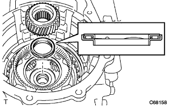
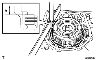
| 60. INSPECT 2ND COAST AND OVERDRIVE BRAKE CLEARANCE |
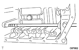
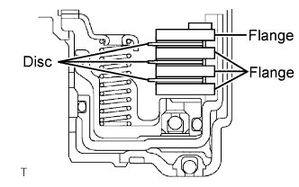
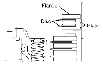
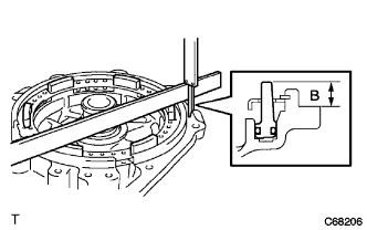
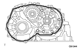
As shown in the illustration, place a straight edge on the transaxle case and measure the distance between the 2nd coast and O/D brake flange and straight edge using vernier calipers. (Dimension A)
As shown in the illustration, place a straight edge on the O/D brake piston and measure the distance between the transaxle rear cover and straight edge using vernier calipers. (Dimension B)
Calculate the piston stroke value using the following formula. Select a flange which meets the piston stroke value and install it.
- Pack clearance:
- 2.091 to 2.491 mm (0.0823 to 0.0981 in.)
- NOTICE:
- If the clearance is outside the specifications, select a new brake flange.
- HINT:
- There are 4 different flange thicknesses.
- Flange thickness:
Mark
| Thickness mm (in.)
| Mark
| Thickness mm (in,)
|
4
| 4.0 (0.1575)
| 6
| 4.4 (0.1732)
|
5
| 4.2 (0.1654)
| 7
| 4.6 (0.1811)
|
| 61. INSTALL REAR CLUTCH DRUM THRUST NEEDLE ROLLER BEARING |
Install the bearing onto the intermediate shaft.
| 62. INSPECT INTERMEDIATE SHAFT ASSEMBLY |
Install the transaxle rear cover with the 11 bolts.
- Torque:
- 25 N*m{250 kgf*cm, 18 ft.*lbf}
Using a dial indicator, measure the clearance of the intermediate shaft.
- Standard clearance:
- 0.204 to 0.966 mm (0.008 to 0.038 in.)
Remove the 11 bolts and the transaxle rear cover.
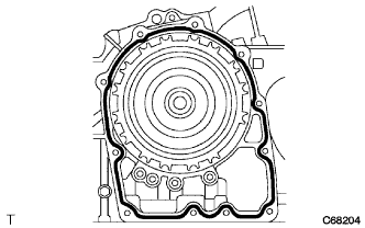
| 63. INSTALL TRANSAXLE CASE GASKET |
Install 4 new gaskets onto the transaxle case.
| 64. INSTALL REAR TRANSAXLE COVER NEEDLE ROLLER BEARING |
Coat a new needle roller bearing with Toyota Genuine ATF WS or equivalent.
Using SST and a press, install the needle roller bearing into the rear transaxle cover.
- SST
- 09950-60010(09951-00190,09952-06010)
09950-70010(09951-07100)
- Standard clearance:
- 25.2 mm (0.992 in.)
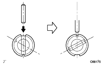
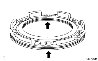
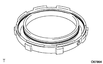
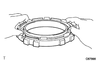
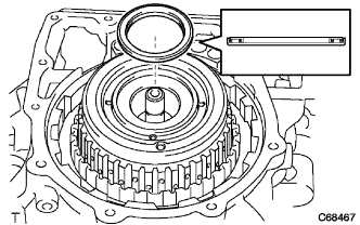
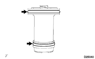
| 65. INSTALL CLUTCH DRUM OIL SEAL RING |
Compress the oil seal ring from both sides to reduce dimension A.
- Dimension A:
- 5.0 mm (0.197 in.)
Coat the oil seal ring with Toyota Genuine ATF WS or equivalent and install it onto the rear transaxle cover.
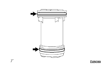
| 66. INSTALL 2ND COAST AND OVERDRIVE O-RING |
Coat 2 new O-rings with Toyota Genuine ATF WS or equivalent and install them into the 2nd coast and overdrive brake piston.
- NOTICE:
- Do not damage the O-rings.
| 67. INSTALL 2ND COAST AND OVERDRIVE BRAKE PISTON |
Coat the piston with Toyota Genuine ATF WS or equivalent and install it into the transaxle rear cover.
- NOTICE:
- Do not damage the O-rings.
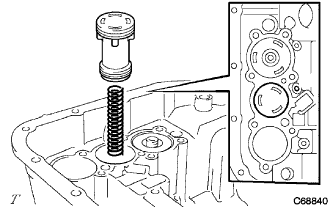
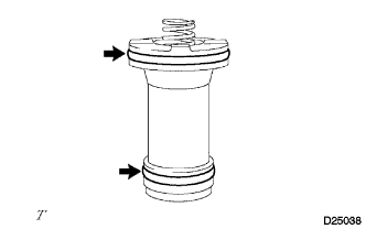
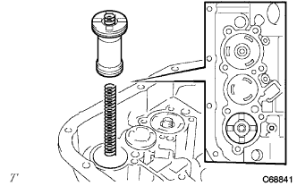
| 68. INSTALL OVERDRIVE BRAKE RETURN SPRING SUB-ASSEMBLY |
Using SST and a press, install the overdrive brake return spring and snap ring onto the transaxle rear cover.
- SST
- 09387-00070
- NOTICE:
- Stop pressing the press when the spring sheet is lowered to 1 to 2 mm (0.039 to 0.078 in.) from the snap ring groove, to prevent the spring sheet from deforming.
- Do not expand the snap ring excessively.
| 69. INSTALL REAR TRANSAXLE COVER PLUG |
Coat 4 new O-rings with Toyota Genuine ATF WS or equivalent, and install them into the 4 rear transaxle cover plugs.
Install the 4 rear transaxle cover plugs into the rear transaxle cover.
- Torque:
- 7.4 N*m{75 kgf*cm, 65 in.*lbf}
- NOTICE:
- Do not damage the O-rings.
| 70. INSTALL REAR TRANSAXLE COVER ASSEMBLY |
Apply FIPG to the transaxle case.
- FIPG:
- Toyota Genuine Seal Packing 1281, Three Bond 1281 or Equivalent
Install the rear transaxle cover with the 11 bolts.
- Torque:
- 25 N*m{250 kgf*cm, 18 ft.*lbf}
| 71. INSTALL FORWARD CLUTCH HUB SUB-ASSEMBLY |
Install the forward clutch hub sub-assembly onto the transaxle case.
| 72. INSTALL FORWARD CLUTCH HUB THRUST NEEDLE ROLLER BEARING |
Install the bearing onto the forward clutch hub.
| 73. INSTALL INPUT SHAFT OIL SEAL RING |
Coat a new input shaft oil seal ring with Toyota Genuine ATF WS or equivalent, and install it into the input shaft.
| 74. INSTALL FORWARD CLUTCH PISTON O-RING |
Coat a new clutch piston O-ring with Toyota Genuine ATF WS or equivalent, and install it into the forward clutch piston.
| 75. INSTALL FORWARD CLUTCH PISTON |
Install the forward clutch piston into the input shaft.
- NOTICE:
- Do not damage the O-ring.
| 76. INSTALL FORWARD CLUTCH RETURN SPRING SUB-ASSEMBLY |
Install the return spring and clutch balancer into the input shaft.
Using SST, a press and snap ring pliers, install the snap ring onto the input shaft.
- SST
- 09320-89010
| 77. INSTALL FRONT CLUTCH CLUTCH DISC |
Install the 4 plates, 4 discs and flange.
Using a screwdriver, install the snap ring into the input shaft.
| 78. INSPECT PACK CLEARANCE OF FORWARD CLUTCH |
Using a dial indicator, measure the pack clearance while applying and releasing compressed air (392 kPa, 4.0 kgf/cm2, 57 psi).
- Pack clearance:
- 1.406 to 1.806 mm (0.05535 to 0.07110 in.)
- NOTICE:
- If the clearance is outside the specifications, select a new brake flange.
- HINT:
- There are 4 different flange thicknesses.
Flange thicknessNo.
| Thickness mm (in.)
| No.
| Thickness mm (in.)
|
-
| 3.0
(0.118)
| 2
| 3.4
(0.134)
|
1
| 3.2
(0.126)
| 3
| 3.6
(0.142)
|
| 79. INSTALL STATOR SHAFT THRUST NEEDLE ROLLER BEARING |
Install the bearing onto the input shaft assembly.
| 80. INSTALL INPUT SHAFT ASSEMBLY |
Install the input shaft assembly onto the transaxle case.
| 81. INSTALL OVERDRIVE BRAKE GASKET |
Install 2 new gaskets onto the transaxle case.
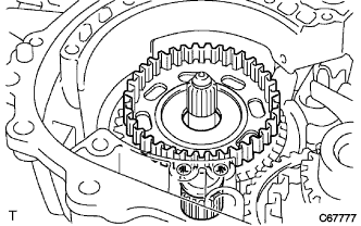
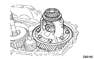
| 82. INSTALL DIFFERENTIAL GEAR ASSEMBLY |
Install the differential gear assembly onto the transaxle case.
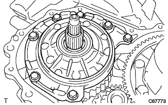
| 83. INSTALL OIL PUMP ASSEMBLY |
Install the oil pump with the 7 bolts.
- Torque:
- 22 N*m{225 kgf*cm, 16 ft.*lbf}
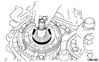
| 84. INSPECT INPUT SHAFT ASSEMBLY |
Make sure that the input shaft turns smoothly.
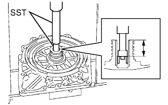
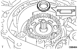
| 85. INSPECT INPUT SHAFT END PLAY |
Measure the end play in the axial direction.
- End play:
- 0.37 to 1.29 mm (0.0146 to 0.0508 in.)
If the end play is not as specified, replace the thrust needle roller bearing.
| 86. INSTALL TRANSAXLE HOUSING |
Apply FIPG to the transaxle case.
- FIPG:
- Toyota Genuine Seal Packing 1281, Three Bond 1281 or Equivalent
Install the transaxle housing with the 14 bolts.
- Torque:
- Bolt A:
- 29 N*m{300 kgf*cm, 22 ft.*lbf}
- Bolt B:
- 22 N*m{225 kgf*cm, 16 ft.*lbf}
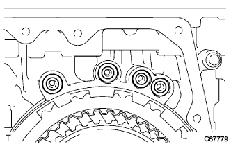
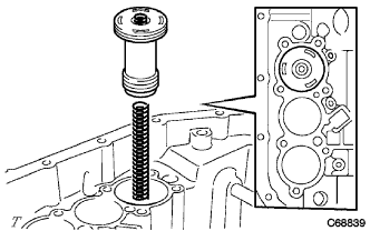
| 87. INSTALL C-2 ACCUMULATOR PISTON |
Coat 2 new O-rings with Toyota Genuine ATF WS or equivalent and install them onto the C-2 accumulator piston.
- NOTICE:
- Do not damage the O-rings.
Install the spring and C-2 accumulator piston.
- Accumulator spring:
Spring
| Free length/
Outer diameter mm (in.)
| Color
|
C-2
| 66.90 (2.6339)
17.20 (0.6772)
| -
|
| 88. INSTALL C-3 ACCUMULATOR PISTON |
Coat 2 new O-rings with Toyota Genuine ATF WS or equivalent and install them onto the C-3 accumulator piston.
- NOTICE:
- Do not damage the O-rings.
Install the spring and C-3 accumulator piston.
- Accumulator spring:
Spring
| Free length/
Outer diameter mm (in.)
| Color
|
C-3
| 80.20 (3.1575)
18.70 (0.7362)
| Blue
|
| 89. INSTALL B-2 ACCUMULATOR PISTON |
Coat 2 new O-rings with Toyota Genuine ATF WS or equivalent and install them onto the B-2 accumulator piston.
- NOTICE:
- Do not damage the O-rings.
Install the spring and B-2 accumulator piston.
- Accumulator spring:
Spring
| Free length/
Outer diameter mm (in.)
| Color
|
B-2
| 66.90 (2.6339)
15.50 (0.6102)
| Green
|
| 90. INSTALL CHECK BALL BODY |
Install the spring and check ball body.
| 91. INSTALL BRAKE DRUM GASKET |
Install a new brake drum gasket.
| 92. INSTALL TRANSAXLE CASE GASKET |
Coat a new transaxle case gasket with Toyota Genuine ATF WS or equivalent, and install it onto the transaxle case.
| 93. INSTALL TRANSAXLE CASE 2ND BRAKE GASKET |
Coat a new transaxle case 2nd brake gasket with Toyota Genuine ATF WS or equivalent, and install it onto the transaxle case.
| 94. INSTALL TRANSMISSION WIRE |
Coat a new O-ring with Toyota Genuine ATF WS or equivalent, and install it onto the transmission wire.
Insert the transmission wire into the transaxle.
Install the transmission wire with the bolt.
- Torque:
- 5.4 N*m{55 kgf*cm, 48 in.*lbf}
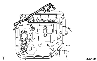
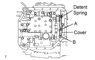
| 95. INSTALL TRANSMISSION VALVE BODY ASSEMBLY |
Align the groove of the manual valve with the pin of the manual valve lever.
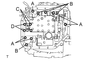
Provisionally install the valve body with the 13 bolts.
- Bolt length:
- Bolt A: 32 mm (1.26 in.)
Bolt B: 22 mm (0.87 in.)
Bolt C: 55 mm (2.17 in.)
Bolt D: 45 mm (1.77 in.)
Provisionally install the detent spring and detent spring cover with the 2 bolts.
- Bolt length:
- Bolt A: 14 mm (0.55 in.)
Bolt B: 45 mm (1.77 in.)
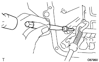
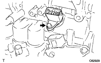
Check that the manual valve lever is in contact with the center of the roller at the tip of the detent spring.
Tighten the 15 bolts.
- Torque:
- 11 N*m{110 kgf*cm, 8 ft.*lbf}
Connect the 5 solenoid connectors.
Install the ATF temperature sensor with the lock plate and bolt.
- Torque:
- 11 N*m{110 kgf*cm, 8 ft.*lbf}
- Bolt length:
- 55 mm (2.17 in.)
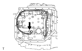
| 96. INSTALL VALVE BODY OIL STRAINER ASSEMBLY |
Coat a new O-ring with Toyota Genuine ATF WS or equivalent, and install it into the oil strainer.
Install the valve body oil strainer assembly onto the automatic transaxle with the 3 bolts.
- Torque:
- 11 N*m{110 kgf*cm, 8 ft.*lbf}
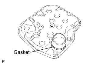
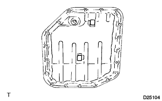
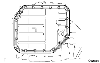
| 97. INSTALL AUTOMATIC TRANSAXLE OIL PAN SUB-ASSEMBLY |
Install the 2 magnets onto the oil pan.
Install a new oil pan gasket onto the oil pan.
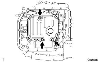
Install the oil pan with the 19 bolts.
- Torque:
- 7.8 N*m{80 kgf*cm, 69 in.*lbf}
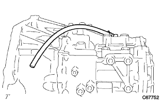
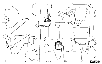
| 98. INSTALL BREATHER PLUG HOSE |
Install the breather plug hose onto the transaxle case.
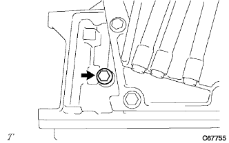
| 99. INSTALL NO. 1 TRANSAXLE CASE PLUG |
Coat 5 new O-rings with Toyota Genuine ATF WS or equivalent, and install them onto the screw plugs.
Install the 4 screw plugs onto the transaxle housing and transaxle case.
- Torque:
- 7.4 N*m{75 kgf*cm, 65 in.*lbf}
Install the screw plug onto the transaxle case.
- Torque:
- 7.4 N*m{75 kgf*cm, 65 in.*lbf}
| 100. INSTALL OIL COOLER TUBE UNION |
Coat 2 new O-rings with Toyota Genuine ATF WS or equivalent, and install them into the 2 oil cooler tube unions.
Install the 2 oil cooler tube unions onto the transaxle case.
- Torque:
- 27 N*m{275 kgf*cm, 20 ft.*lbf}
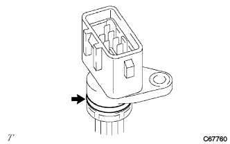
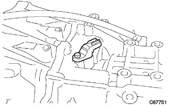
| 101. INSTALL TRANSMISSION REVOLUTION SENSOR |
Coat a new O-ring with Toyota Genuine ATF WS or equivalent, and install it into the transmission revolution sensor.
Install the transmission revolution sensor onto the transaxle case with the bolt.
- Torque:
- 5.4 N*m{55 kgf*cm, 48 in.*lbf}
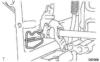
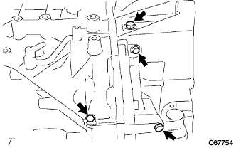
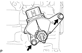
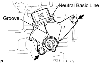
| 102. INSTALL PARK/NEUTRAL POSITION SWITCH ASSEMBLY |
Install the park/neutral position switch assembly onto the manual transaxle.
Provisionally install the 2 bolts.
Replace the lock plate with a new one and tighten the manual valve shaft nut.
- Torque:
- 6.9 N*m{70 kgf*cm, 61 in.*lbf}
Provisionally install the control shaft lever.
Turn the lever counterclockwise until it stops, then turn it clockwise 2 notches.
Remove the control shaft lever.
Align the groove with the neutral basic line.
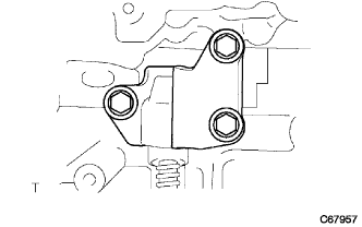
Hold the switch in this position and tighten the 2 bolts.
- Torque:
- 5.4 N*m{55 kgf*cm, 48 in.*lbf}
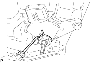
Using a screwdriver, stake the nut with the lock plate.
Install the control shaft lever with the nut and washer.
- Torque:
- 13 N*m{130 kgf*cm, 9 ft.*lbf}
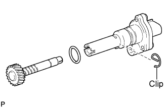
| 103. INSTALL SPEEDOMETER DRIVEN GEAR |
Coat a new O-ring with Toyota Genuine ATF WS or equivalent and install it into the speedometer sensor.
Install the driven gear into the speedometer sensor with the clip.
| 104. INSTALL SPEEDOMETER SENSOR |
Install the speedometer sensor onto the transaxle housing.