Automatic Transaxle Assembly (For Sedan) -- Installation |
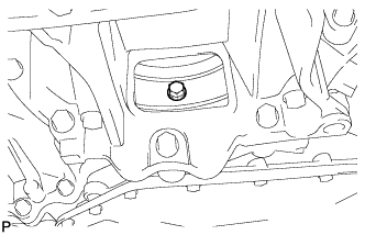
| 1. INSTALL TRANSMISSION OIL FILLER TUBE SUB-ASSEMBLY |
Apply Toyota Genuine ATF WS or equivalent to a new O-ring, and install it onto the oil filler tube.
Install the oil filler tube onto the automatic transaxle with the bolt.
- Torque:
- 5.5 N*m{56 kgf*cm, 49 in.*lbf}
 |
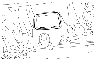
| 2. INSTALL TRANSMISSION OIL LEVEL GAUGE SUB-ASSEMBLY |
Install the oil level gauge into the oil filler tube.
| 3. INSTALL NO. 2 OIL COOLER TUBE CLAMP |
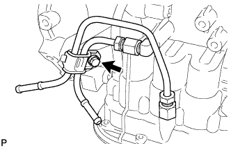 |
Provisionally install outlet No. 1 oil cooler tube into the oil cooler tube union.
Provisionally install inlet No. 1 oil cooler tube into the oil cooler tube union.
Provisionally install No. 2 oil cooler tube clamp onto the oil level gauge with the bolt.
- Torque:
- 5.5 N*m{56 kgf*cm, 49 in.*lbf}
| 4. INSTALL OUTLET NO. 1 OIL COOLER TUBE |
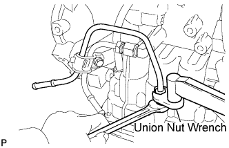 |
Using a union nut wrench, install the outlet No. 1 oil cooler tube while holding the oil cooler tube union with a wrench.
- Torque:
- For use without union nut wrench:
- 34 N*m{347 kgf*cm, 25 ft.*lbf}
- For use with union nut wrench:
- 32 N*m{327 kgf*cm, 24 ft.*lbf}
- HINT:
- This torque value can be obtained by using a torque wrench with a fulcrum length of 345 mm (13.58 in.) and a union nut wrench with a fulcrum length of 30 mm (1.18 in.).
- This torque value is effective when the union nut wrench is parallel to the torque wrench.
| 5. INSTALL INLET NO. 1 OIL COOLER TUBE |
 |
Using a union nut wrench, install the inlet No. 1 oil cooler tube while holding the oil cooler tube union with a wrench.
- Torque:
- For use without union nut wrench:
- 34 N*m{347 kgf*cm, 25 ft.*lbf}
- For use with union nut wrench:
- 32 N*m{327 kgf*cm, 24 ft.*lbf}
- HINT:
- This torque value can be obtained by using a torque wrench with a fulcrum length of 345 mm (13.58 in.) and a union nut wrench with a fulcrum length of 30 mm (1.18 in.).
- This torque value is effective when the union nut wrench is parallel to the torque wrench.
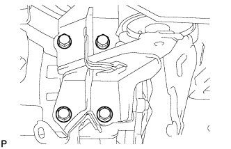
| 6. INSTALL NO. 1 TRANSMISSION CONTROL CABLE BRACKET |
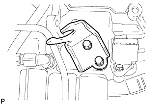 |
Install No. 1 transmission control cable bracket onto the automatic transaxle with the 2 bolts.
- Torque:
- 12 N*m{122 kgf*cm, 9 ft.*lbf}
| 7. INSPECT TORQUE CONVERTER CLUTCH ASSEMBLY |
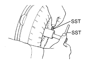 |
Inspect the one-way clutch.
Install SST so that it fits into notch of the converter hub and the notch of the outer race of the one-way clutch.
- SST
- 09350-32014(09351-32010,09351-32020)
Press on the serrations of the stator with a finger and rotate it.
Check that it rotates smoothly when turned clockwise and locks up when turned counterclockwise.- SST
- 09350-32014(09351-32010,09351-32020)
Replace the converter if the one-way clutch still does not operate as specified.
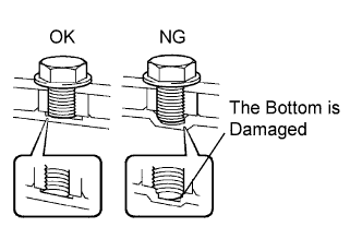
Check the condition of the torque converter clutch assembly.
If the inspection result of the torque converter clutch assembly meets any of the cases mentioned below, replace the torque converter clutch.
- Malfunction Item:
- Any metallic sound is heard from the torque converter clutch during stall test or when the shift lever is in the N position.
The one-way clutch is released or locked in both directions.
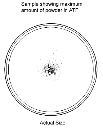
Fine powder exceeding the sample limit is identified in ATF.
(See the sample.)
- HINT:
- The sample shows approximately. 0.25 liters (0.26 US qts, 0.22 lmp. qts) of ATF that is taken out from the removed torque converter clutch.
 |
Replace the ATF in the torque converter clutch.
If the ATF is discolored and/or has a foul odor, completely stir the ATF in the torque converter clutch and drain it with the installation surface facing up.
Clean and check the oil cooler and oil pipe line.
If the torque converter clutch is inspected or the ATF is changed, clean the oil cooler and oil pipe line.
- HINT:
- Spray compressed air of 196 kpa (2 kgf/cm2, 28 psi) from the inlet hose.
- If excessive fine powder is found in the ATF, add new ATF using a bucket pump and clean it again.
If the ATF is cloudy, inspect the oil cooler (radiator).

| 8. INSTALL TORQUE CONVERTER CLUTCH ASSEMBLY |
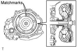
Set the key at the top of the front oil pump drive gear and put a mark on the housing.
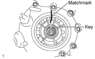 |
Put a mark on the torque converter so that its groove is clearly indicated.
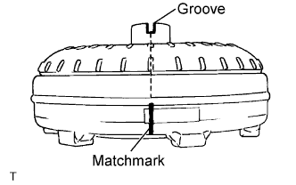 |
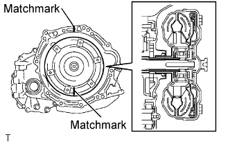
Align the mark on the case with the one on the torque converter and fit the spline of the input shaft to the spline of the turbine runner.
 |
Rotating the torque converter, fit the spline of the stator shaft with that of the stator.
- HINT:
- Rotate it approximately 180 degrees.
 |
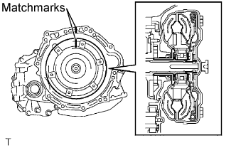
Rotating the torque converter, align the mark on the case with the one on the torque converter again and fit the key of the oil pump drive gear into the keyway of the torque converter.
- NOTICE:
- Do not push the converter excessively when rotating it.
 |
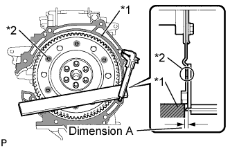
Using a vernier caliper and a straightedge, measure the dimension A between the automatic transaxle fitting surface (*1) of the engine and the torque converter fitting surface (*2) of the drive plate.
- NOTICE:
- Subtract the thickness of the straightedge from the measured value to gain dimension A.
- HINT:
- The converter fitting surface and the ring gear side surface are at the same level.
 |
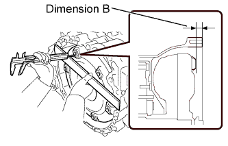
Using a vernier caliper and a straightedge, measure dimension B shown in the illustration and check that dimension B is greater than dimension A, which was measured in step (f).
- Standard:
- A + 1 mm (0.04 in.) or more
- NOTICE:
- Subtract the thickness of the straightedge from the measured value to gain dimension B.
 |
| 9. INSTALL AUTOMATIC TRANSAXLE ASSEMBLY |
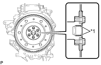
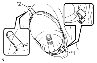
Apply clutch spline grease to the round of the crankshaft contact surface (*1) with the torque converter centerpiece.
- Clutch spline grease:
- Toyota Genuine Clutch Spline Grease or equivalent
- Maximum spread:
- Approximately 1 g (0.353 oz)
 |
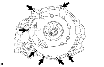
Install the automatic transaxle onto the engine with the 7 bolts.
- Torque:
- 30 N*m{306 kgf*cm, 22 ft.*lbf}
- NOTICE:
- Confirm that 2 knock pins are on the transaxle fitting surface of the engine block before transaxle installation.
- After installing the transmission, confirm that the torque converter rotates smoothly.
 |
Remove any adhesive remaining in the 6 bolt holes of the torque converter clutch and 6 bolts.
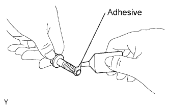 |
Apply adhesive to 2 or 3 threads on the end of the 6 bolts.
- Adhesive:
- Toyota Genuine Adhesive 1324, Three Bond 1324 or equivalent
Install the 6 torque converter set bolts while holding the crankshaft pulley bolt with a wrench.
- Torque:
- 28 N*m{286 kgf*cm, 21 ft.*lbf}
 |
Install the flywheel housing under cover.
 |
| 10. INSTALL ENGINE MOUNTING BRACKET LH |
Remove any adhesive remaining in the 4 bolt holes on the engine mounting bracket LH and 4 bolts.
|
Apply adhesive to 2 or 3 threads on the end of the 4 bolts.
- Adhesive:
- Toyota Genuine Adhesive 1324, Three Bond 1324 or equivalent
Install the engine mounting bracket LH onto the automatic transaxle with the 4 bolts.
- Torque:
- 64 N*m{653 kgf*cm, 47 ft.*lbf}
 |
| 11. INSTALL ENGINE MOUNTING INSULATOR LH |
 |
Install the engine mounting insulator LH and the engine mounting bracket LH with the bolt and nut.
- Torque:
- 52 N*m{530 kgf*cm, 38 ft.*lbf}
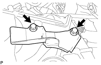
| 12. INSTALL ENGINE MOVING CONTROL ROD BRACKET |
 |
Install the engine moving control bracket onto the automatic transaxle with the 3 bolts.
- Torque:
- 39 N*m{398 kgf*cm, 29 ft.*lbf}
| 13. INSTALL FRONT SUSPENSION CROSSMEMBER SUB-ASSEMBLY |
Place wooden blocks or plate lift attachments on an engine lifter, and then set the front suspension crossmember sub-assembly so that the attachments are in the positions shown in the illustration.
Text in Illustration 
Front of the Vehicle 
Attachment Placement Positions
 |
Provisionally install the front suspension crossmember onto the body with the 6 bolts.
By inserting SST into the datum holes in the front suspension crossmembers RH and LH alternately, tighten bolts A, B and C on both sides to the specified torque, in several steps.
- SST
- 09670-00011
- Torque:
- Bolt A:
- 87 N*m{887 kgf*cm, 64 ft.*lbf}
- Bolt B:
- 151 N*m{1540 kgf*cm, 111 ft.*lbf}
- Bolt C:
- 98 N*m{999 kgf*cm, 72 ft.*lbf}
- NOTICE:
- Insert SST into the datum hole in a vertical orientation.
- If SST cannot be inserted into the datum hole vertically, loosen all the bolts and then insert SST again.
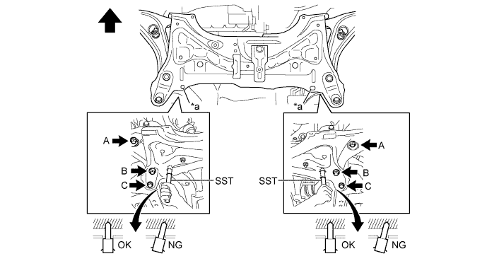
Text in Illustration *a Datum Hole - - Front of the Vehicle - -
Install the engine moving control rod with the bolt.
- Torque:
- 120 N*m{1224 kgf*cm, 89 ft.*lbf}
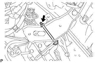
| 14. INSTALL ENGINE MOVING CONTROL ROD |
 |
Install the engine moving control rod and the engine moving control bracket with the bolt and nut.
- Torque:
- 120 N*m{1,224 kgf*cm, 89 ft.*lbf}
| 15. INSTALL OUTLET OIL COOLER HOSE |
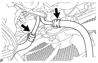 |
Install the outlet oil cooler hose onto the outlet oil cooler tube.
| 16. INSTALL INLET OIL COOLER HOSE |
Install the inlet oil cooler hose onto the inlet oil cooler tube.
| 17. INSTALL FRONT DRIVE SHAFT ASSEMBLY LH |
for Automatic Transaxle:
Coat the spline of the inboard joint with ATF.
for Manual Transaxle:
Coat the spline of the inboard joint with gear oil.
Align the inboard joint splines and install the drive shaft with a screwdriver and hammer.
- NOTICE:
- Face the cut area of the front drive inboard joint hole snap ring downward.
- Do not damage the oil seal.
- Do not damage the inboard joint boot.
- HINT:
- Confirm whether the drive shaft is securely driven in by checking the reaction force and sound.
 |
| 18. INSTALL FRONT DRIVE SHAFT ASSEMBLY RH |
- HINT:
- The installation procedure for the RH side is the same as that for the LH side.
| 19. INSTALL AUTOMATIC TRANSMISSION CASE PROTECTOR (w/o ABS) |
 |
Remove the 2 bolts and remove the transmission case protector from the automatic transaxle.
| 20. INSTALL FRONT AXLE ASSEMBLY LH |
 |
Install the front axle assembly onto the shock absorber.
Install the 2 bolts and 2 nuts.
- Torque:
- 164 N*m{1,672 kgf*cm, 121 ft.*lbf}
- HINT:
- Keep the nut from rotating while turning the bolt.
Push the front axle out of the vehicle to align the spline of the drive shaft with the front axle and insert the front axle.
- NOTICE:
- Do not push the front axle further out of the vehicle than is necessary.
- Do not damage the outboard joint boot.
- Check for any foreign matter on the speed sensor rotor and insertion part.
- Do not damage the speed sensor rotor.
| 21. INSTALL FRONT AXLE ASSEMBLY RH |
- HINT:
- Use the same procedure for the LH side and RH side.
| 22. INSTALL FRONT LOWER SUSPENSION ARM LH |
Install the lower arm onto the steering knuckle with a new castle nut.
- Torque:
- 98 N*m{999 kgf*cm, 72 ft.*lbf}
- NOTICE:
- If the holes for the clip are not aligned, tighten the nut by a further turn of up to 60°.
Install a new clip.
| 23. INSTALL FRONT LOWER SUSPENSION ARM RH |
- HINT:
- Use the same procedure for the LH side and RH side.
| 24. INSTALL TIE ROD END SUB-ASSEMBLY LH |
Install the tie rod end sub-assembly onto the steering knuckle with a new castle nut.
- Torque:
- 49 N*m{500 kgf*cm, 36 ft.*lbf}
- NOTICE:
- If the holes for the clip are not aligned, tighten the nut by a further turn of up to 60°.
Install a new cotter pin.
| 25. INSTALL TIE ROD END SUB-ASSEMBLY RH |
- HINT:
- Use the same procedure for the LH side and RH side.
| 26. INSTALL FRONT STABILIZER LINK ASSEMBLY LH |
Install the front stabilizer link assembly with the nut.
- Torque:
- 74 N*m{755 kgf*cm, 55 ft.*lbf}
- HINT:
- If the ball joint turns together with the nut, use a socket hexagon wrench 6 to hold the stud.
| 27. INSTALL FRONT STABILIZER LINK ASSEMBLY RH |
- HINT:
- Use the same procedure for the LH side and RH side.
| 28. INSTALL FRONT SPEED SENSOR LH (w/ ABS) |
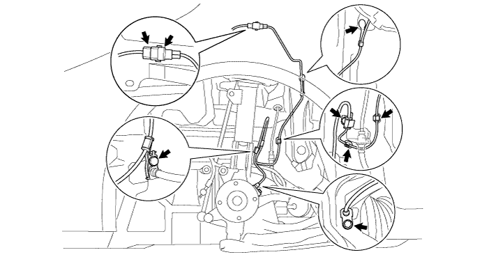
Install the speed sensor onto the steering knuckle with the bolt.
- Torque:
- 8.5 N*m{87 kgf*cm, 75 in.*lbf}
- NOTICE:
- Check that the speed sensor tip and installation portion are free of foreign matter.
- Install the speed sensor without turning it from its original installation angle.
Install the clamp onto the shock absorber with the bolt.
- Torque:
- 29 N*m{300 kgf*cm, 22 ft.*lbf}
Install the clamp onto the body with the bolt.
- Torque:
- 6.0 N*m{61 kgf*cm, 53 in.*lbf}
Install the 3 clips.
Connect the speed sensor connector.
Install the speed sensor clip onto the body.
| 29. INSTALL FRONT SPEED SENSOR RH (w/ ABS) |
- HINT:
- Use the same procedure for the LH side and RH side.
| 30. INSTALL FRONT AXLE HUB NUT LH |
 |
Using a 30 mm socket wrench, install a new axle hub nut.
- Torque:
- 216 N*m{2,203 kgf*cm, 160 ft.*lbf}
Using a chisel and hammer, caulk the axle hub nut.
| 31. INSTALL FRONT AXLE HUB NUT RH |
- HINT:
- Use the same procedure for the LH side and RH side.
| 32. INSTALL STARTER ASSEMBLY |
 |
Install the starter assembly with the 2 bolts.
- Torque:
- 37 N*m{377 kgf*cm, 27 ft.*lbf}
Connect the connector.
Connect terminal 30 with the nut.
- Torque:
- 9.8 N*m{100 kgf*cm, 87 in.*lbf}
Close the terminal cap.
| 33. CONNECT WIRE HARNESS |
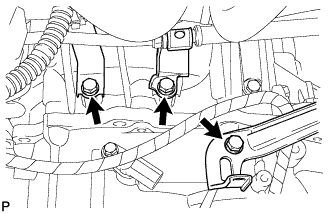 |
Install the 3 wire harness clamp brackets onto the automatic transaxle with the 3 bolts.
- Torque:
- 5.0 N*m{51 kgf*cm, 44 in.*lbf}
| 34. CONNECT CONNECTOR |
Connect the vehicle speed sensor connector.
Connect the transmission revolution sensor connector.
Connect the transmission wire connector and install the clamp onto the engine mount insulator.
Connect the park neutral position switch connector and install the clamp onto the engine mount insulator.
| 35. INSTALL NO. 3 ENGINE WIRE |
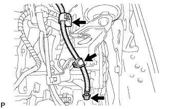 |
Install No. 3 engine wire onto the automatic transaxle with the bolt.
- Torque:
- 26 N*m{260 kgf*cm, 19 ft.*lbf}
Install the 2 clamps onto the engine mount insulator.
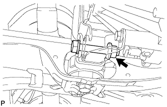
| 36. INSTALL TRANSMISSION CONTROL CABLE ASSEMBLY |
 |
Install the transmission control cable onto the control shaft lever with the nut.
- Torque:
- 12 N*m{122 kgf*cm, 9 ft.*lbf}
Install the transmission control cable into the bracket with the new clip.
| 37. INSTALL NO. 1 STEERING COLUMN HOLE COVER SUB-ASSEMBLY |
Install clip B onto the body portion and install No. 1 steering column hole cover sub-assembly onto the body portion with clip A.
Text in Illustration *1 Clip A *2 Clip B - NOTICE:
- Make sure that the lip portion of No. 1 steering column hole cover sub-assembly is not damaged.
 |
| 38. INSTALL STEERING SLIDING YOKE SUB-ASSEMBLY |
Align the matchmarks and install the sliding yoke onto the intermediate shaft with bolt B.
Text in Illustration *1 Bolt A *2 Bolt B *a Matchmark - Torque:
- 35 N*m{360 kgf*cm, 26 ft.*lbf}
 |
Tighten bolt A.
- Torque:
- 35 N*m{360 kgf*cm, 26 ft.*lbf}
| 39. INSTALL COLUMN HOLE COVER SILENCER SHEET |
Install the column hole cover silencer sheet with the 2 clips.
Install the floor carpet.
| 40. INSTALL AIR CLEANER BRACKET |
Install the air cleaner bracket with the 2 bolts.
- Torque:
- 19 N*m{194 kgf*cm, 14 ft.*lbf}
Connect the wire harness clamp to the air cleaner bracket.
| 41. INSTALL AIR CLEANER ASSEMBLY |
Install the air cleaner case with air cleaner inlet No. 1 with the 2 bolts.
- Torque:
- 7.8 N*m{80 kgf*cm, 69 in.*lbf}
Connect the wire harness to the air cleaner case.
Install the air cleaner element.
Install and lock the air cleaner cap and the air cleaner hose and then tighten the air cleaner hose clamp.
- Torque:
- 4.0 N*m{41 kgf*cm, 35 in.*lbf}
Connect the ventilation hose to the air cleaner hose.
Connect the vacuum switching valve connector and the wire harness clamp.
Connect the fuel vapor feed hose to the vacuum switching valve assembly and air cleaner hose.
Connect the intake air flow meter connector and the wire harness clamp.
| 42. INSTALL NO. 2 CYLINDER HEAD COVER |
Tighten the 2 A nuts, then the 2 B nuts.
- Torque:
- 7.0 N*m{71 kgf*cm, 62 in.*lbf}
| 43. INSTALL BATTERY CARRIER |
Install the battery carrier with the 5 bolts.
- Torque:
- 17 N*m{173 kgf*cm, 13 ft.*lbf}
Install the clamp.
| 44. INSTALL BATTERY TRAY |
| 45. INSTALL BATTERY |
Install the battery onto the vehicle with the battery clamp.
- Torque:
- 3.5 N*m{36 kgf*cm, 31 in.*lbf}
Connect the cable to the battery terminal.
- Torque:
- 5.4 N*m{55 kgf*cm, 48 in.*lbf}
| 46. INSTALL OUTER COWL TOP PANEL |
Install the cowl top panel outer with the 8 bolts.
- Torque:
- 6.5 N*m{66 kgf*cm, 58 in.*lbf}
Install the cowl top to cowl inner brace with the 2 bolts.
- Torque:
- 6.5 N*m{66 kgf*cm, 58 in.*lbf}
Connect the wire harness clamp.
| 47. INSTALL FRONT AIR SHUTTER SEAL |
Engage the 3 claws to install the front air shutter seal RH.
| 48. INSTALL FRONT WIPER MOTOR AND LINK |
Connect the connector.
 |
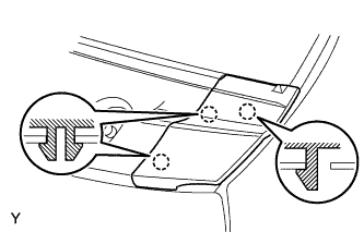
Slide the wiper link as shown in the illustration and engage the rubber pin with the body.
Install the front wiper motor and link with the 2 bolts.
- Torque:
- 5.5 N*m{56 kgf*cm, 49 in.*lbf}
| 49. INSTALL COWL TOP VENTILATOR LOUVER SUB-ASSEMBLY |
Connect the washer hoses.
 |
Engage the 5 hooks.
Engage the 8 hooks and the 4 claws.
 |
Install the cowl top ventilator louver sub-assembly with the 3 clips.
| 50. INSTALL COWL SIDE VENTILATOR SUB-ASSEMBLY LH |
Engage the 3 claws and install the cowl side ventilator sub-assembly LH.
 |
| 51. INSTALL COWL SIDE VENTILATOR SUB-ASSEMBLY RH |
- HINT:
- Use the same procedure as for the LH side.
| 52. INSTALL FRONT WIPER ARM AND BLADE ASSEMBLY LH |
Scrape any metal powder off the serrated part of the wiper arm with a round file or the equivalent (when reinstalling).
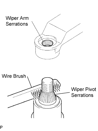 |
Clean the wiper pivot serrations with a wire brush.
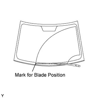
Operate the wiper, then stop the windshield wiper motor in the automatic stop position.
Align the blade tip with the mark on the windshield glass, as shown in the illustration.
 |
Tighten the nut of the front wiper arm.
- Torque:
- 26 N*m{265 kgf*cm, 19 ft.*lbf}
| 53. INSTALL FRONT WIPER ARM AND BLADE ASSEMBLY RH |
Scrape any metal powder off the serrated part of the wiper arm with a round file or the equivalent (when reinstalling).
|
Clean the wiper pivot serrations with a wire brush.
Operate the wiper, then stop the windshield wiper motor in the automatic stop position.
Align the blade tip with the mark on the windshield glass, as shown in the illustration.
 |
Tighten the nut of the front wiper arm.
- Torque:
- 26 N*m{265 kgf*cm, 19 ft.*lbf}
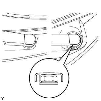
| 54. INSTALL FRONT WIPER ARM HEAD CAP |
Engage the claw and install the 2 front wiper arm head caps.
 |
| 55. TEMPORARILY TIGHTEN HOOD SUB-ASSEMBLY |
Provisionally install the hood with the 4 bolts.
- HINT:
- Tighten the bolts to the specified torque after inspecting the hood.
| 56. INSPECT HOOD SUB-ASSEMBLY |
Check that the clearance measurements are within the standard ranges.
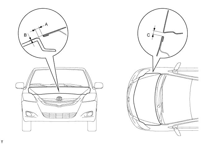
- Standard:
Area Measurement Area Measurement A 2.35 to 6.35 mm
(0.092 to 0.250 in.)C 2.0 to 5.0 mm
(0.079 to 0.197 in.)B -2 to 2 mm
(-0.079 to 0.079 in.)- -
| 57. ADJUST HOOD SUB-ASSEMBLY |
Loosen the hood side hinge bolts.
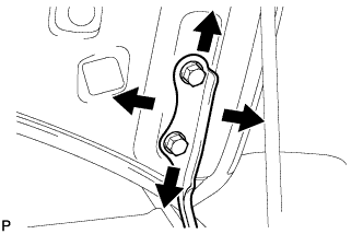 |
Move the hood to adjust the clearance to within the standard range.
Tighten the hood side hinge bolts after the adjustment.
- Torque:
- 13 N*m{133 kgf*cm, 10 ft.*lbf}
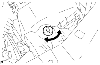
Adjust the height of the hood front end by turning the cushion rubber.
- HINT:
- The cushion rubber can be raised and lowered by turning it.
 |
Adjust the hood lock.
Loosen the 3 bolts.
Adjust the hood lock position so that the striker can enter it smoothly.
Tighten the 3 bolts after the adjustment.
- Torque:
- 7.5 N*m{76 kgf*cm, 66 in.*lbf}
 |
| 58. ADD AUTOMATIC TRANSAXLE FLUID |
| Classification | Capacity (Reference) | |
| Toyota Genuine ATF WS or equivalent | Dry fill | 6.4 liters (6.8 US qts, 5.6 Imp. qts) |
| Drain and refill | 2.5 liters (2.6 US qts, 2.2 Imp. qts) | |
| 59. INSPECT AUTOMATIC TRANSAXLE FLUID |
 |
- HINT:
- Drive the vehicle until the engine and transaxle are at normal operating temperature.
- Fluid temperature:
- 70 to 80 °C (158 to 176 °F)
Park the vehicle on a level surface and engage the parking brake.
With the engine idling and the brake pedal depressed, shift the shift lever into all positions from P to L, and then return it to the P position.
Pull out the oil level gauge and wipe it clean.
Push it fully back into the pipe.
Pull it out and check that the fluid level is within the HOT range.
If there is any leakage, repair or replace O-rings, FIPGs, oil seals, plugs or other parts.
| 60. CHECK AUTOMATIC TRANSAXLE FLUID LEAKAGE |
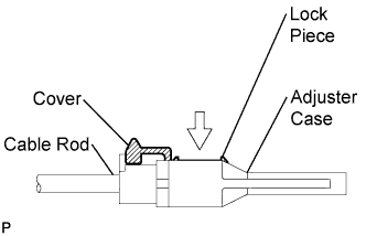
| 61. ADJUST SHIFT LEVER POSITION |
Shift the shift lever to the N position.
Slide the adjuster case cover in the direction shown in the illustration and pull out the lock piece.
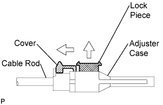 |
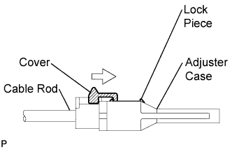
Gently pull the cable rod toward the rear of the vehicle by hand to pull the cable taut.
Press the lock piece into the adjuster case and lock it.
 |
Slide the cover in the direction shown in the illustration.
- NOTICE:
- Slide the cover past the protrusion of the lock piece.
 |
Inspect the operation after the adjustment.
| 62. INSPECT SHIFT LEVER POSITION |
When shifting the lever from P to the R position with the ignition switch ON and the brake pedal depressed, make sure that the shift lever moves smoothly and moves correctly into position.
Start the engine and make sure that the vehicle moves forward when shifting the lever from N to the D position and moves rearward when shifting the lever to the R position.
If the operation cannot be performed as specified, inspect the park/neutral position switch assembly and check the shift lever assembly installation condition.
| 63. INSTALL ENGINE UNDER COVER RH |
| 64. INSTALL ENGINE UNDER COVER LH |
| 65. INSTALL FRONT WHEELS |
- Torque:
- 103 N*m{1050 kgf*cm, 76 ft.*lbf}
| 66. INSPECT AND ADJUST FRONT WHEEL ALIGNMENT |