Engine Hybrid System. Yaris. Ncp93, 131
Cruise Control. Yaris. Ncp93, 131
Cruise Control System (For Sedan) -- Terminals Of Ecm |
| CHECK ECM |
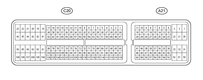
Measure the voltages of the wire harness side connectors.
| Symbols (Terminals No.) | Wiring Color | Terminal Description | Condition | Specified Condition |
| TC (A21-27) - E1 (C20-104) | P - W | DTC output signal | Ignition switch ON | 10 to 14 V |
| TC (A21-27) - E1 (C20-104) | P - W | DTC output signal | Ignition switch ON Connect terminals TC and CG of DLC3 | Below 2 V |
| ST1- (A21-35) - E1 (C20-104) | Y - W | Cruise cancel input signal | Ignition switch ON Depress brake pedal | Below 1 V |
| ST1- (A21-35) - E1 (C20-104) | Y - W | Cruise cancel input signal | Ignition switch ON Release brake pedal | 10 to 14 V |
| STP (A21-36) - E1 (C20-104) | G - W | Stop light switch input signal | Ignition switch ON Depress brake pedal | 10 to 14 V |
| STP (A21-36) - E1 (C20-104) | G - W | Stop light switch input signal | Ignition switch ON Release brake pedal | Below 1 V |
| CCS (A21-40) - E1 (C20-104) | L - W | Cruise control main switch output signal | Ignition switch ON | 10 to 14 V |
| CCS (A21-40) - E1 (C20-104) | L - W | Cruise control main switch output signal | Ignition switch ON CANCEL switch held ON | 6.6 to 10.1 V |
| CCS (A21-40) - E1 (C20-104) | L - W | Cruise control main switch output signal | Ignition switch ON -/SET switch held ON | 4.5 to 7.1 V |
| CCS (A21-40) - E1 (C20-104) | L - W | Cruise control main switch output signal | Ignition switch ON +/RES switch held ON | 2.3 to 4.5 V |
| CCS (A21-40) - E1 (C20-104) | L - W | Cruise control main switch output signal | Ignition switch ON MAIN switch held ON | Below 1 V |
| E1 (C20-104) - Body ground | W - Body ground | Ground | Always | Below 1 V |
| D (C20-56) - E1 (C20-104)*1 | L - W | Clutch switch input signal | Ignition switch ON Depress clutch pedal | Below 1 V |
| D (C20-56) - E1 (C20-104)*1 | L - W | Clutch switch input signal | Ignition switch ON Release clutch pedal | 10 to 14 V |
| D (C20-56) - E1 (C20-104)*2 | L - W | Park/neutral position switch signal | Ignition switch ON Shift lever not in D | Below 1 V |
| D (C20-56) - E1 (C20-104)*2 | L - W | Park/neutral position switch signal | Ignition switch ON Shift lever in D | 10 to 14 V |
| CANH (A21-41) - E1 (C20-104) | L - W | CAN communication line | Ignition switch ON | Pulse generation (see waveform 1) |
| CANL (A21-49) - E1 (C20-104) | W - W | CAN communication line | Ignition switch ON | Pulse generation (see waveform 2) |
- *1: for Manual Transaxle
- *2: for Automatic Transaxle
| WAVEFORM 1(Reference) |
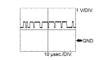 |
| ECM Terminal Names | Between CANH and E1 |
| Tester Ranges | 1 V/DIV, 10 μs/DIV |
| Conditions | Engine stops and ignition switch ON |
- HINT:
- The waveform varies depending on the CAN communication signal.
| WAVEFORM 2(Reference) |
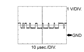 |
| ECM Terminal Names | Between CANL and E1 |
| Tester Ranges | 1 V/DIV, 10 μs/DIV |
| Conditions | Engine stops and ignition switch ON |
- HINT:
- The waveform varies depending on the CAN communication signal.