Starter (For Hatchback For Cold Area Specification Vehicles) -- Reassembly |
| 1. INSTALL STARTER CENTER BEARING CLUTCH SUB-ASSEMBLY |
Apply high-temperature grease to the parts of the starter pinion drive lever that contact the starter pivot part of the starter pinion drive lever.
Text in Illustration *1 Starter Pinion Drive Lever *2 Rubber Seal *3 Starter Center Bearing Clutch Sub-Assembly 
High-temperature grease
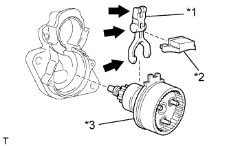 |
Install the starter pinion drive lever and rubber seal into the starter center bearing clutch sub-assembly.
Install the starter center bearing clutch together with the starter pinion drive lever into the starter drive housing assembly.
| 2. INSTALL PLANETARY GEAR |
Apply high-temperature grease to the planetary gears and pin parts of the planetary shaft.
Text in Illustration High-temperature grease
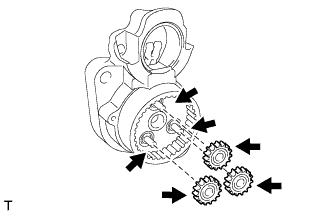 |
Install the 3 planetary gears.
| 3. INSTALL STARTER BRUSH HOLDER ASSEMBLY |
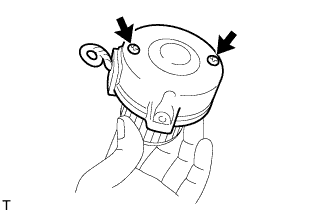
Install the brush holder.
Using a screwdriver, hold the brush springs back, and install the 4 brushes into the brush holder.
Install the brush holder to the starter armature.
Insert the grommet between the positive (+) pole and negative (-) pole.
Text in Illustration *1 Grommet *2 - Pole *3 + Pole

 |
| 4. INSTALL STARTER COMMUTATOR END FRAME ASSEMBLY |
Fit the clamp of the brush holder into the starter commutator end frame assembly.
 |
Install the commutator end frame with the 2 screws.
- Torque:
- 1.5 N*m{15 kgf*cm, 13 in.*lbf}
 |
| 5. INSTALL STARTER ARMATURE ASSEMBLY |
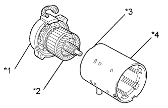
Align the rubber with the groove of the starter yoke assembly.
Install the starter armature with the brush holder onto the starter yoke assembly.
- NOTICE:
- The magnet of the starter yoke assembly may attract the starter armature assembly when the starter commutator end frame assembly is installed, causing the magnet to break.
- HINT:
- Support the starter armature so that it may not be pulled out from the starter brush holder by magnetic force of the starter yoke assembly.
Text in Illustration *1 Starter Commutator End Frame Assembly *2 Starter Armature Assembly *3 Groove *4 Starter Yoke Assembly
 |
| 6. INSTALL STARTER ARMATURE PLATE |
Install the starter armature plate onto the starter yoke assembly.
Install the starter plate so that the keyway is positioned between the keys.
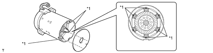
Text in Illustration *1 Key - -
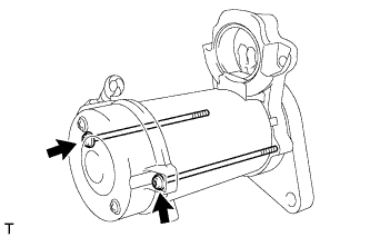
| 7. INSTALL STARTER COMMUTATOR END FRAME ASSEMBLY |
Align the key of the starter yoke with the keyway located on the starter drive housing assembly.
Text in Illustration *1 Key *2 Keyway
 |
Using a T25 "TORX" socket wrench, install the drive housing with the 2 bolts.
- Torque:
- 6.0 N*m{61 kgf*cm, 53 in.*lbf}
 |
| 8. INSTALL MAGNET STARTER SWITCH ASSEMBLY |
Apply high-temperature grease to the plunger hook.
Hang the plunger of the magnet starter switch assembly into the drive lever from the upper side.
 |
Install the magnet starter switch assembly with the 2 nuts.
- Torque:
- 7.5 N*m{77 kgf*cm, 66 in.*lbf}
 |
Connect the lead wire to the magnet starter switch, then fasten it with the nut.
- Torque:
- 10 N*m{102 kgf*cm, 7.4 ft.*lbf}
 |