Cylinder Block (For Hatchback) -- Reassembly |
| 1. INSTALL CYLINDER BLOCK WATER DRAIN COCK SUB-ASSEMBLY |
Apply adhesive to the end 2 or 3 threads of the drain union and install the water drain cock within 3 minutes of applying the adhesive.
- Adhesive:
- Toyota Genuine Adhesive 1324, Three Bond 1324 or equivalent
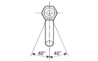
After applying the specified torque, rotate the drain union clockwise until the drain port faces downward.
- Torque:
- 35 N*m{357 kgf*cm, 26 ft.*lbf}
- NOTICE:
- Do not put into coolant within 1 hour of installation.
- Do not rotate the drain union more than 360° in step (b), and never loosen it after setting the union correctly.
 |
| 2. INSTALL STRAIGHT PIN |
Using a plastic-faced hammer, tap in the straight pin.
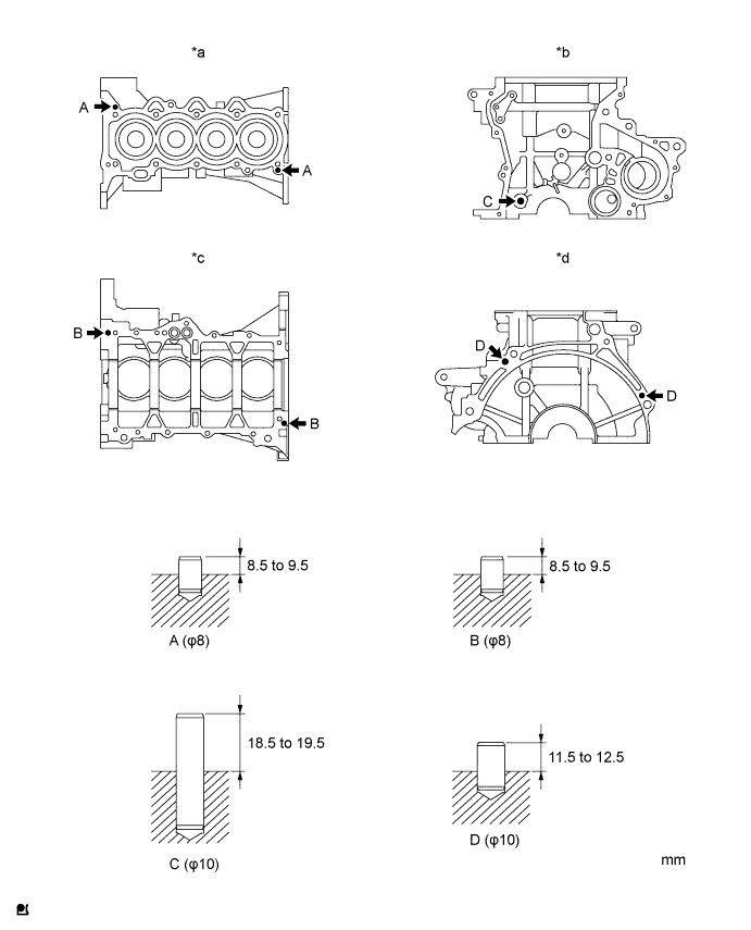
Text in Illustration *a Upper Side *b Front Side *c Lower Side *d Rear Side - Standard protrusion:
- Pin A:
- 8.5 to 9.5 mm (0.335 to 0.374 in.)
- Pin B:
- 8.5 to 9.5 mm (0.335 to 0.374 in.)
- Pin C:
- 18.5 to 19.5 mm (0.728 to 0.768 in.)
- Pin D:
- 11.5 to 12.5 mm (0.453 to 0.492 in.)
| 3. INSTALL OIL PUMP SET RING PIN |
Using a plastic-faced hammer, tap in a new ring pin.
- Standard protrusion:
- 3.5 to 4.5 mm (0.138 to 0.177 in.)
 |
| 4. INSTALL STUD BOLT |
Install the 7 stud bolts.
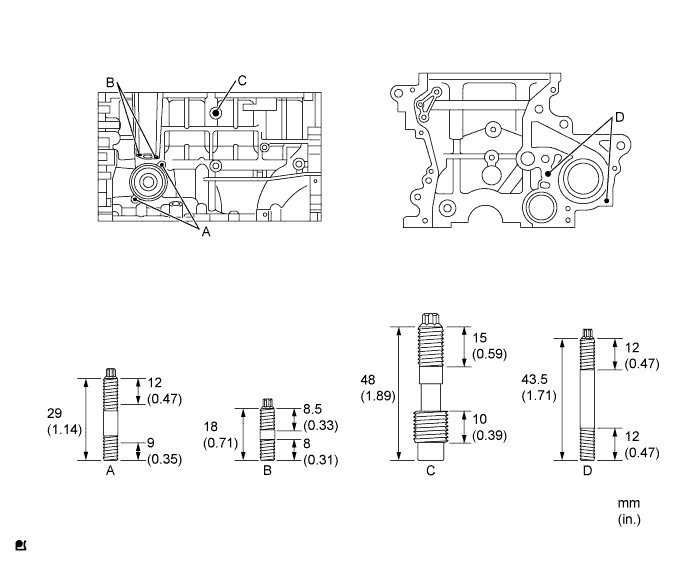
- Torque:
- Stud bolts A, B and D:
- 5.0 N*m{51 kgf*cm, 44 in.*lbf}
- Stud bolt C:
- 11 N*m{112 kgf*cm, 8 ft.*lbf}
- NOTICE:
- The lower threads of the bolt are installed into the cylinder block.
| 5. INSTALL CRANKSHAFT BEARING |
 |
Align the crankshaft bearing (upper) with the oil hole of the cylinder block and install the bearing.
Text in Illustration *a Incorrect *b Correct - NOTICE:
- Do not apply engine oil to the bearing or its contact surface.
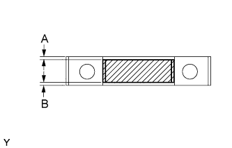
Align the crankshaft bearing (lower) with the bearing cap and install the crankshaft bearing cap.
- NOTICE:
- Install the bearing cap so that the gap between A and B is less than 0.4 mm (0.016 in.).
- Do not apply engine oil to the bearing or its contact surface.
 |
| 6. INSTALL CRANKSHAFT THRUST WASHER UPPER |
 |
Install the 2 thrust washers onto the No. 3 journal position of the cylinder block with the oil grooves facing outward.
Apply engine oil to the upper bearing and install the crankshaft onto the cylinder block.
| 7. INSTALL CRANKSHAFT |
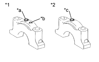
Examine the front marks and numbers and install the bearing caps onto the cylinder block.
Text in Illustration *1 No. 3 Bearing Cap *2 No. 1,2,4,5 Bearing Cap *a Front Mark *b Number *c Front Mark and Number
 |
Apply a light coat of engine oil to the threads of the bearing cap bolts.
Tighten the bolts in several steps to the specified torque in the sequence shown in the illustration (*1).
- Torque:
- 22 N*m{224 kgf*cm, 16 ft.*lbf}
- NOTICE:
- Check that the crankshaft turns smoothly.
 |
Mark the front of the bearing cap bolts with paint.
Text in Illustration *a Paint Mark 
Engine Front
 |
Further tighten the bearing cap bolts by 90° in the same sequence as step (*1).
Check that the painted mark is now at a 90° angle from the front.
| 8. INSPECT CRANKSHAFT THRUST CLEARANCE |
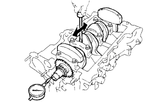 |
Using a dial indicator, measure the thrust clearance while moving the crankshaft back and forth with a screwdriver.
- Standard thrust clearance:
- 0.09 to 0.19 mm (0.0035 to 0.0075 in.)
- Maximum thrust clearance:
- 0.30 mm (0.0118 in.)
- HINT:
- Thrust washer thickness: 2.43 to 2.48 mm (0.0957 to 0.976 in.)
| 9. INSPECT CRANKSHAFT OIL CLEARANCE |
Clean each main journal and bearing.
Install the bearing onto the cylinder block and bearing cap. (YARIS_NCP93 RM000001DFS02PX.html)
Place the crankshaft onto the cylinder block.
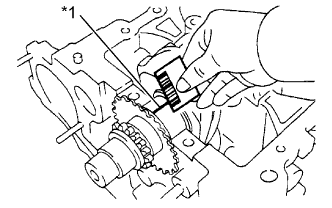
Lay a strip of Plastigage across each journal.
Text in Illustration *1 Plastigage
 |
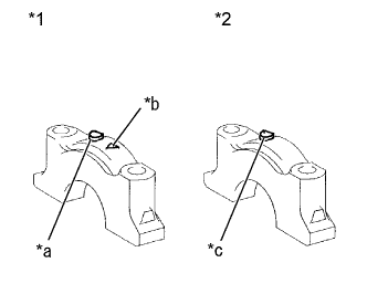
Examine the front marks and numbers and install the bearing cap onto the cylinder block.
Text in Illustration *1 No. 3 Bearing Cap *2 No. 1,2,4,5 Bearing Cap *a Front Mark *b Number *c Front Mark and Number
 |
Apply a light coat of engine oil to the threads of the bearing cap bolts.
Using SST, tighten the bolts in several steps to the specified torque in the sequence shown in the illustration. (*1)
- Torque:
- 22 N*m{224 kgf*cm, 16 ft.*lbf}
|
Mark the front of the bearing cap bolts with paint.
Text in Illustration *a Paint Mark Engine Front
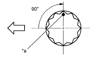 |
Further tighten the bearing cap bolts by 90° in the same sequence as step (*1).
Check that the painted mark is now at a 90° angle from the front.
- NOTICE:
- Do not turn the crankshaft.
Remove the bearing cap sub-assembly.
Measure the Plastigage at its widest point.
Text in Illustration *1 Plastigage - Standard oil clearance:
- 0.01 to 0.023 mm (0.0004 to 0.0009 in.)
- Maximum oil clearance:
- 0.07 mm (0.0028 in.)
- NOTICE:
- Completely remove the Plastigage after the measurement.
 |
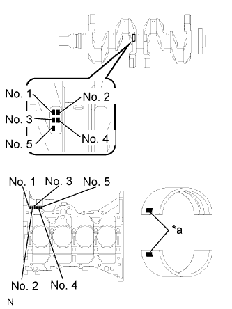
When replacing a standard bearing, replace it with one with the same number. If the number of the bearing cannot be found, select the correct bearing by adding together the numbers imprinted on the cylinder block and crankshaft, then select the bearing with the same number as the total. There are 4 sizes of standard bearings, marked 1, 2, 3 and 4 accordingly.
Text in Illustration *a Mark EXAMPLE: Cylinder Block 4 (A) + Crankshaft 3 (B) = Total 7 (Use Bearing 3) Cylinder Block (A)
+
Crankshaft (B)0 to 2 3 to 5 6 to 8 9 to 11 Use Bearing 1 2 3 4 Item Mark mm (in.) Cylinder block main journal bore diameter (A) 0
1
2
3
4
5
650.000 to 50.003 (1.96850 to 1.96862)
50.003 to 50.005 (1.96862 to 1.96870)
50.005 to 50.007 (1.96870 to 1.96878)
50.007 to 50.010 (1.96878 to 1.96890)
50.010 to 50.012 (1.96890 to 1.96898)
50.012 to 50.014 (1.96898 to 1.96906)
50.014 to 50.016 (1.96906 to 1.96913)Crankshaft main journal diameter (B) 0
1
2
3
4
545.998 to 46.000 (1.81094 to 1.81102)
45.996 to 45.998 (1.81087 to 1.81094)
45.994 to 45.996 (1.81079 to 1.81087)
45.992 to 45.994 (1.81071 to 1.81079)
45.990 to 45.992 (1.81063 to 1.81071)
45.988 to 45.990 (1.81055 to 1.81063)Standard bearing center wall thickness 1
2
3
41.992 to 1.995 (0.07843 to 0.07854)
1.995 to 1.998 (0.07854 to 0.07866)
1.998 to 2.001 (0.07866 to 0.07878)
2.001 to 2.004 (0.07878 to 0.07890)
 |
| 10. INSTALL WITH PIN PISTON SUB-ASSEMBLY |
Coat the piston pin and pin holes in the piston with engine oil.
Text in Illustration *a Front Mark
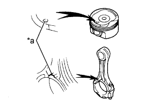 |
Align the cavity of the piston with the protruding portion on the connecting rod.
Using SST, press in the piston pin.
Text in Illustration *1 Connecting Rods *2 Piston Pin *3 Piston - SST
- 09221-25026(09221-00021,09221-00030,09221-00150,09221-00090,09221-00100)
 |
| 11. INSTALL CONNECTING ROD BEARING |
Align the bearing claw with the groove of the connecting rod or connecting cap.
Text in Illustration *a Claw - NOTICE:
- Clean the back side of the bearing and the bearing surface of the connecting rod and keep them free of oil.
 |
| 12. INSTALL PISTON RING SET |
 |
- HINT:
- When reusing the piston rings, install them onto the matched pistons with the surfaces facing correctly.
Install the oil ring expander and 2 side rails by hand.
Using a piston ring expander, install the 2 compression rings.
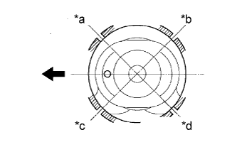
Position the piston rings so that the ring ends are as shown.
Text in Illustration *a No. 1 Compression and Expander *b Lower Side Rail *c Upper Side Rail *d No. 2 Compression 
Engine Front
 |
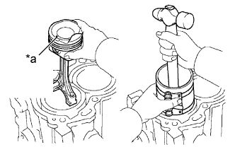
| 13. INSTALL PISTON SUB-ASSEMBLY WITH CONNECTING ROD |
Apply engine oil to the cylinder walls, the pistons, and the surfaces of connecting rod bearings.
Check the position of the piston ring ends.
Using a piston ring compressor, push the correctly numbered piston and connecting rod assemblies into each cylinder with the front mark on the piston facing forward.
Text in Illustration *a Front Mark - NOTICE:
- Clean the back side of the bearing and the bearing surface of the connecting rod cap and keep them free of oil.
- Match the numbered connecting rod cap with the connecting rod.
 |
Make sure that the connecting rod and cap are in the correct combination and that the front mark of the cap is facing in the correct mounting orientation, then install the cap onto the connecting rod.
Text in Illustration *a Front Mark
 |
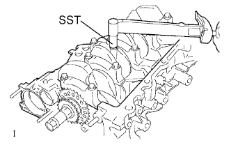
Apply a light coat of engine oil to the threads of the connecting rod cap bolts.
Using SST, tighten the bolts in several steps to the specified torque.
- SST
- 09205-16011
- Torque:
- 15 N*m{153 kgf*cm, 11 ft.*lbf}
 |
Mark the front of the connecting cap bolts with paint.
Text in Illustration *a Paint Mark Engine Front
 |
Further tighten the cap bolts by 90° as shown.
Check that the crankshaft turns smoothly.