Cylinder Head (For Hatchback) -- Inspection |
| 1. INSPECT CYLINDER HEAD FOR WARPAGE |
Using a precision straightedge and feeler gauge, measure the warpage of the surface that is in contact with the cylinder block and the manifolds.
Text in Illustration *a Cylinder Block Side *b Intake Manifold Side *c Exhaust Manifold Side - Maximum Warpage:
Surface Specified Condition Cylinder block side 0.05 mm (0.0020 in.) Intake manifold side 0.10 mm (0.0039 in.) Exhaust manifold side 0.10 mm (0.0039 in.)
 |
| 2. INSPECT CYLINDER HEAD FOR CRACKS |
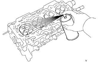
Using a dye penetrant, check the combustion chamber, intake ports, exhaust ports and cylinder block surface for cracks.
If cracked, replace the cylinder head.
 |
| 3. INSPECT INTAKE VALVE |
Check the overall valve length.
Text in Illustration *a Overall Length - Standard overall length:
- 89.25 mm (3.5138 in.)
- Minimum overall length:
- 88.75 mm (3.4941 in.)
 |
Using a micrometer, measure the diameter of the valve stem.
- Standard valve stem diameter:
- 4.970 to 4.985 mm (0.1957 to 0.1963 in.)
 |
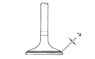
Check the valve head margin thickness.
Text in Illustration *a Margin Thickness - Standard margin thickness:
- 1.0 mm (0.039 in.)
- Minimum margin thickness:
- 0.5 mm (0.020 in.)
 |
| 4. INSPECT EXHAUST VALVE |
Check the overall valve length.
- Standard overall length:
- 87.90 mm (3.4606 in.)
- Minimum overall length:
- 87.40 mm (3.4409 in.)
Using a micrometer, measure the diameter of the valve stem.
- Standard valve stem diameter:
- 4.965 to 4.980 mm (0.1955 to 0.1961 in.)
Check the valve head margin thickness.
- Standard margin thickness:
- 1.15 mm (0.045 in.)
- Minimum margin thickness:
- 0.5 mm (0.020 in.)
| 5. INSPECT VALVE SPRING |
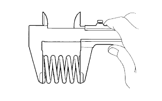
Using a vernier caliper, measure the free length of the valve spring.
- Standard free length:
- 45.05 to 45.15 mm (1.774 to 1.778 in.)
 |
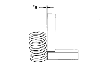
Using a steel square, measure the deviation of the valve spring.
Text in Illustration *a Deviation - Maximum deviation:
- 1.6 mm (0.063 in.)
- Maximum angle (reference):
- 2°
 |
| 6. INSPECT VALVE GUIDE BUSH OIL CLEARANCE |
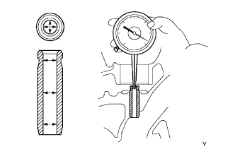
Using a caliper gauge, measure the inside diameter of the guide bush.
- Bush inside diameter:
- 5.010 to 5.030 mm (0.1972 to 0.1980 in.)
 |
Subtract the valve stem diameter measurement from the guide bush inside diameter measurement.
- Standard Oil Clearance:
Guide Bush Specified Condition Intake 0.025 to 0.060 mm
(0.0010 to 0.0024 in.)Exhaust 0.030 to 0.065 mm
(0.0012 to 0.0026 in.)
- Maximum Oil Clearance:
Guide Bush Specified Condition Intake 0.08 mm (0.0032 in.) Exhaust 0.10 mm (0.0039 in.)
| 7. INSPECT INTAKE VALVE SEAT |
Apply a light coat of Prussian blue to the valve face.
Lightly press the valve against the seat.
Check the valve face and seat according to the following procedure.
Text in Illustration *a Width If blue appears 360° around the face, the valve is concentric. If not, replace the valve.
If blue appears 360° around the valve seat, the guide and face are concentric. If not, resurface the seat.
Check that the seat contact is in the middle of the valve face with the width between 1.0 to 1.4 mm (0.039 to 0.055 in.).
 |
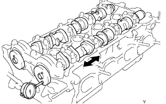
| 8. INSPECT CAMSHAFT THRUST CLEARANCE |
Install the camshafts (YARIS_NCP93 RM000001DCP016X_01_0002.html).
Using a dial indicator, measure the thrust clearance while moving the camshaft back and forth.
- Standard thrust clearance:
- 0.040 to 0.095 mm (0.0016 to 0.0037 in.)
- Maximum thrust clearance:
- 0.11 mm (0.0043 in.)
 |
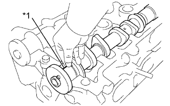
| 9. INSPECT CAMSHAFT OIL CLEARANCE |
Clean the bearing caps and the camshaft journals.
Place the camshafts on the cylinder head.
Lay a strip of Plastigage across each of the camshaft journals.
Text in Illustration *1 Plastigage
 |
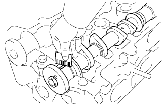
Install the bearing caps (YARIS_NCP93 RM000001DCP016X_01_0002.html).
- NOTICE:
- Do not turn the camshaft.
Remove the bearing caps.
Measure the Plastigage at its widest point.
- Standard oil clearance:
- 0.035 to 0.072 mm (0.0014 to 0.0028 in.)
- Maximum oil clearance:
- 0.08 mm (0.0031 in.)
- NOTICE:
- Completely remove the Plastigage.
 |