Cylinder Head Gasket (For Sedan) -- Installation |
| 1. INSTALL CYLINDER HEAD GASKET |
 |
Place a new cylinder head gasket on the cylinder block with the Lot No. stamp facing upward.
Text in Illustration *a Lot No. - NOTICE:
- Remove any oil from the contact surfaces.
- Check the mounting orientation of the cylinder head gasket.
- Place the cylinder head on the cylinder head gently in order not to damage the gasket.
| 2. INSTALL CYLINDER HEAD SUB-ASSEMBLY |
- HINT:
- The cylinder head bolts are tightened in 2 successive steps.
Apply a light coat of engine oil to the threads of the cylinder head bolts.
Using several steps, install and tighten the 10 cylinder head bolts and plate washers uniformly with an 8 mm bi-hexagon wrench, in the sequence shown in the illustration.
- Torque:
- 29 N*m{300 kgf*cm, 22 ft.*lbf}
 |
Mark the front of the cylinder head bolt with paint.
Retighten the cylinder head bolts 90° and then an additional by 90° as shown in the illustration.
Text in Illustration *a Paint Mark
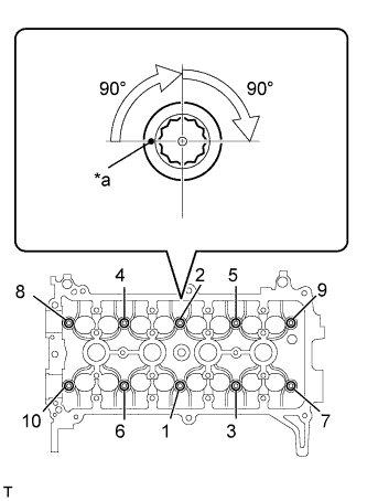 |
Check that the paint mark is now at a 180° angle from the front.
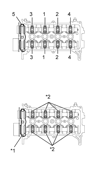
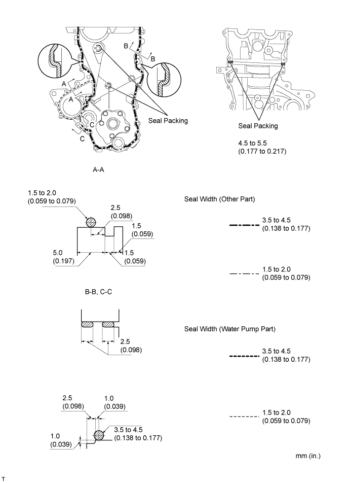
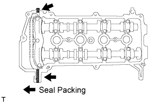
Apply a continuous bead of seal packing (Diameter 4.5 to 5.5 mm (0.177 to 0.217 in.)) as shown in the illustration.
- Seal Packing:
- Toyota Genuine Seal Packing Black, Three Bond 1207B or Equivalent
Text in Illustration *1 Cylinder Head *2 Cylinder Head Gasket *3 Cylinder Block *a Seal Packing *b Diameter: 4.5 to 5.5 mm - NOTICE:
- Remove any oil from the contact surfaces.
- Install the oil pump assembly within 3 minutes and tighten the bolts within 15 minutes of applying the seal packing.
 |
| 3. INSTALL CAMSHAFT |
 |
Examine the front marks and numbers and check that the sequence is as shown in the illustration. Then provisionally tighten the 19 bolts.
Uniformly tighten the bolts in several steps in the sequence shown in the illustration and install No. 1 camshaft bearing cap and No. 2 camshaft bearing cap.
Text in Illustration *1 No. 1 Bearing Cap *2 No. 2 Bearing Cap - Torque:
- No. 1 Camshaft bearing cap:
- 23 N*m{235 kgf*cm, 17 ft.*lbf}
- No. 2 Camshaft bearing cap:
- 13 N*m{129 kgf*cm, 9 ft.*lbf}
- NOTICE:
- Tighten each bolt uniformly while keeping the camshaft level.
 |
| 4. INSTALL CHAIN SUB-ASSEMBLY |
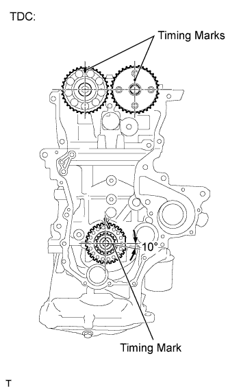 |
Make sure that all the timing marks are in the positions (TDC) shown in the illustration.
- HINT:
- The positions of the timing marks may differ the predetermined positions due to the force of the valve spring.
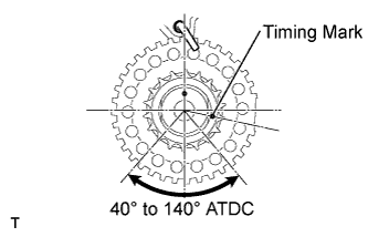
Set the timing mark of the crankshaft in a position between 40 and 140° ATDC, as illustrated.
 |
Set the camshaft timing gear and the camshaft timing sprocket in the positions (20° ATDC) shown in the illustration.
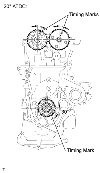 |
Set the crankshaft in the position (20° ATDC) shown in the illustration.
Install the No. 1 chain vibration damper with the 2 bolts.
- Torque:
- 9.0 N*m{92 kgf*cm, 80 in.*lbf}
 |
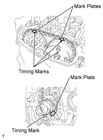
Align the timing marks of the camshaft with the mark plates of the timing chain and install the timing chain.
- HINT:
- Align the timing marks with the mark plates while turning the hexagonal service portion of the camshaft using a wrench.
 |
| 5. INSTALL CHAIN TENSIONER SLIPPER |
 |
Install the chain tensioner slipper.
| 6. INSTALL NO. 1 CHAIN TENSIONER ASSEMBLY |
 |
Install the No. 1 chain tensioner assembly with the 2 bolts.
- Torque:
- 9.0 N*m{92 kgf*cm, 80 in.*lbf}
Remove the bar from the No. 1 chain tensioner assembly.
| 7. INSTALL OIL PUMP SEAL |
 |
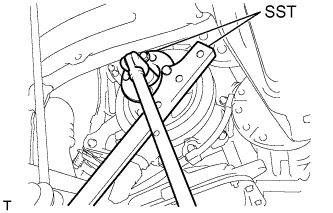
Using SST and a hammer, tap in a new oil seal until its surface is flush with the timing chain cover edge.
- SST
- 09950-60010(09951-00250,09951-00410,09952-06010)
09950-70010(09951-07100)
- NOTICE:
- Do not tap the oil seal at an angle.
Apply a light coat of MP grease to the oil pump seal lip.
- NOTICE:
- Keep the seal lip free of foreign matter.
| 8. INSTALL OIL PUMP ASSEMBLY |
 |
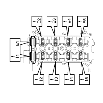
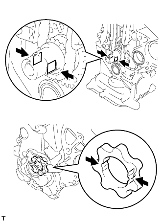
Install 2 new O-rings onto the 2 locations shown in the illustration.
Apply seal packing to the oil pump assembly, cylinder head and cylinder block as shown in the illustration.
- Seal packing:
- Water pump part Toyota Genuine Seal Packing 1282B, Three Bond 1282B or equivalent
- Other part Toyota Genuine Seal Packing Black, Three Bond 1207B or equivalent
- NOTICE:
- Remove any oil from the contact surfaces.
- Install the oil pump assembly within 3 minutes and tighten the bolts and nut within 15 minutes of applying seal packing.
- Do not expose the seal to engine oil for at least 2 hours after the installation.
Align the keyway of the oil pump rotor with the rectangular portion of the crankshaft, and slide the oil pump into place.
 |
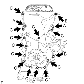
Install the oil pump assembly with the 15 bolts and the nut. Tighten the bolts and nut uniformly in several steps.
- Torque:
- 32 N*m{326 kgf*cm, 24 ft.*lbf}for bolt A
- 11 N*m{112 kgf*cm, 8 ft.*lbf}for bolt B
- 11 N*m{112 kgf*cm, 8 ft.*lbf}for bolt C
- 24 N*m{245 kgf*cm, 18 ft.*lbf}for nut D
- 24 N*m{245 kgf*cm, 18 ft.*lbf}for bolt E
- NOTICE:
- After installing the oil pump assembly, install the mounting bracket and water pump within 15 minutes.
- HINT:
- Each bolt length is as follows.
- A: 30 mm (1.181 in.)
- B: 35 mm (1.378 in.)
- C: 20 mm (0.787 in.)
- E: 14 to 20 mm (0.551 to 0.787 in.), Double ended bolt
 |
| 9. INSTALL TRANSVERSE ENGINE ENGINE MOUNTING BRACKET |
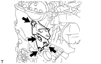 |
Install the transverse engine engine mounting bracket with the 4 bolts.
- Torque:
- 55 N*m{561 kgf*cm, 41 ft.*lbf}
| 10. INSTALL ENGINE WATER PUMP ASSEMBLY |
Install the engine water pump assembly through a new gasket with the 3 bolts and 2 nuts.
- Torque:
- 11 N*m{112 kgf*cm, 8.1 ft.*lbf}
| 11. INSTALL WATER PUMP PULLEY |
Provisionally install the water pump pulley with the 3 bolts.
Using SST, hold the engine water pump pulley.
- SST
- 09960-10010(09962-01000,09963-00700)
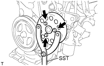 |
Tighten the 3 bolts to the specified torque.
- Torque:
- 15 N*m{153 kgf*cm, 11 ft.*lbf}
| 12. INSTALL CAMSHAFT TIMING OIL CONTROL VALVE ASSEMBLY |
 |
Apply a light coat of engine oil to a new O-ring and install it onto the camshaft timing oil control valve assembly.
- NOTICE:
- Do not twist the O-ring.
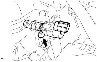
Install the camshaft timing oil control valve assembly with the bolt.
- Torque:
- 7.5 N*m{76 kgf*cm, 66 in.*lbf}
 |
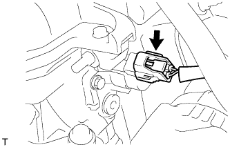
Connect the camshaft timing oil control valve assembly connector.
 |
| 13. INSTALL CRANKSHAFT POSITION SENSOR |
 |
Apply a light coat of engine oil to the O-ring on the crankshaft position sensor.
Install the crankshaft position sensor with the bolt.
- Torque:
- 7.5 N*m{76 kgf*cm, 66 in.*lbf}
- NOTICE:
- Do not twist the O-ring.
Connect the crankshaft position sensor connector.
| 14. INSTALL CRANKSHAFT DAMPER SUB-ASSEMBLY |
Align the pin hole of the crankshaft damper with the pin and install the crankshaft damper sub-assembly.
Provisionally install the bolt.
Using 2 SSTs, tighten the bolt while holding the crankshaft damper sub-assembly.
- SST
- 09213-14010(91651-60865)
09330-00021
- Torque:
- 128 N*m{1305 kgf*cm, 95 ft.*lbf}
- NOTICE:
- Check the SST installation positions when installing them, to avoid the SST fixing bolts from coming into contact with the oil pump assembly.
 |
| 15. INSTALL ENGINE MOUNTING INSULATOR SUB-ASSEMBLY RH |
Install the engine mounting insulator sub-assembly RH with the 5 bolts and nut.
- Torque:
- 52 N*m{530 kgf*cm, 38 ft.*lbf}
 |
| 16. INSTALL CYLINDER HEAD COVER SUB-ASSEMBLY |
Install a new gasket to the cylinder head cover sub-assembly.
Apply seal packing to the cylinder head as shown in the illustration.
- Seal Packing:
- Toyota Genuine Seal Packing Black, Three Bond 1207B or Equivalent
- NOTICE:
- Remove any oil from the contact surface.
- Install the cylinder head cover sub-assembly within 3 minutes of applying the seal packing.
- Do not start the engine for at least 2 hours after the installation.
 |
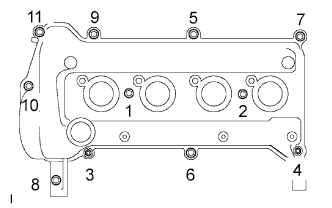
Install the cylinder head cover sub-assembly with the 9 bolts, 2 nuts and 2 seal washers.
Tighten the 9 bolts and 2 nuts in the sequence shown in the illustration.
- Torque:
- 10 N*m{102 kgf*cm, 7.0 ft.*lbf}
 |
Install the wire harness bracket with the bolt.
- Torque:
- 13 N*m{133 kgf*cm, 9.6 ft.*lbf}
 |
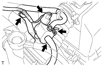
Connect the connector and wire harness clamp shown in the illustration and connect the engine wire harness.
 |
Connect the fuel injector connectors.
 |
| 17. INSTALL FUEL VAPOR FEED HOSE ASSEMBLY |
 |
Connect fuel vapor feed hose assembly.
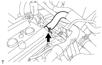
| 18. INSTALL VENTILATION HOSE |
 |
Connect the ventilation hose.
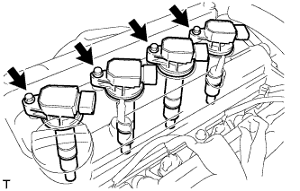
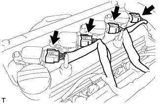
| 19. INSTALL NO. 1 IGNITION COIL |
Install the 4 ignition coils with the 4 bolts.
- Torque:
- 9.0 N*m{92 kgf*cm, 80 in.*lbf}
- NOTICE:
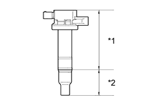
- If the body or cap of the ignition coil is dropped or subjected to a strong impact, replace the ignition coil with a new one.
Text in Illustration *1 Body *2 Cap
 |
Connect the 4 ignition coil connectors.
 |
| 20. INSTALL GENERATOR ASSEMBLY |
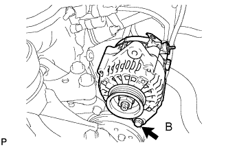 |
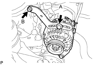
Provisionally install the generator with fixing bolt B.
Provisionally install the fan belt adjusting slider with fan belt adjusting slider fixing bolts A and B, then move the generator toward the cylinder block and tighten bolt B.
- Torque:
- 11 N*m{112 kgf*cm, 8.1 ft.*lbf}
 |
Install the connector and the wire harness clamp.
 |
Install terminal B with the nut.
- Torque:
- 9.8 N*m{100 kgf*cm, 7.2 ft.*lbf}
Install the terminal cap.
| 21. INSTALL FAN AND GENERATOR V BELT |
Provisionally install the fan and generator V belt onto each pulley.
- NOTICE:
- Make sure that there is no foreign matter or liquid, such as oil, on the belt and pulleys.
- Make sure that the V belt is securely fitted into the rib grooves of the pulley.
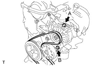
| 22. ADJUST FAN AND GENERATOR V BELT |
Insert an adjusting bar between the engine mounting bracket and generator assembly. Pull the adjusting bar toward the vehicle front to adjust the generator V belt tension (YARIS_NCP93 RM000001DCH00ZX_01_0001.html).
Text in Illustration *a OK *b NG - NOTICE:
- Do not insert the adjusting bar between the camshaft timing oil control valve assembly and generator assembly. It could damage the camshaft timing oil control valve assembly.
 |
First tighten bolt A, then tighten bolt B.
- Torque:
- 19 N*m{189 kgf*cm, 14 ft.*lbf} for bolt A
- 54 N*m{551 kgf*cm, 40 ft.*lbf} for bolt B
 |
| 23. INSPECT FAN AND GENERATOR V BELT |
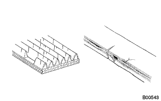 |
Check the belt for wear, cracks or other signs of damage.
If any of the following defects is found, replace the V-ribbed belt.- HINT:
- The belt is cracked.
- The belt is worn out to the extent that the wires are exposed.
- The belt has chunks missing from the ribbed groves.
Check that the belt fits properly in the ribbed grooves.
Text in Illustration *a CORRECT *b INCORRECT - HINT:
- Check with your hand, to confirm that the belt has not slipped out of the grooves on the bottom to the pulley. If it has slipped out, replace the V-ribbed belt. Install a new V-ribbed belt correctly.
 |
Inspect the V belt deflection and tension.
Text in Illustration *A w/o Air Conditioner *B w/ Air Conditioner - Deflection:
Item Specified Condition New belt 8.0 to 9.0 mm (0.31 to 0.35 in) Used belt 12.5 to 13.5 mm (0.49 to 0.53 in)
- Tension:
Item Specified Condition New belt 700 to 800 N (71 to 82 kg, 157 to 180 lb) Used belt 300 to 400 N (31 to 41 kg, 67 to 90 lb)
- HINT:
- When inspecting the V belt deflection, apply 98 N (10 kgf) tensile force to it.
- Perform the V belt inspection and adjustment while the engine is cold.
- V-ribbed belt tension and deflection should be checked immediately after installation of a new belt, and after cranking the engine when inspecting a used belt.
- Check the V belt deflection at the point between the specified pulleys where the deflection is greatest.
- When installing a new belt, set its tension to the intermediate value of the specification.
- When inspecting a belt which has been used for over 5 minutes, apply the Used Belt specifications.
- When reinstalling a belt which has been used for over 5 minutes, adjust its deflection and tension to the intermediate values of each Used Belt specification.
- V-ribbed belt tension and deflection should be checked after 2 revolutions of engine cranking.
- When using a belt tension gauge, confirm its accuracy by using a master gauge first.
 |
| 24. INSTALL MANIFOLD SUPPORT BRACKET |
Install the manifold support bracket with the 3 bolts.
- Torque:
- 44 N*m{449 kgf*cm, 33 ft.*lbf}
| 25. INSTALL FRONT EXHAUST PIPE ASSEMBLY |
 |
Using vernier calipers, measure the free length of the compression spring.
- Minimum length:
- 40.5 mm (1.594 in.)
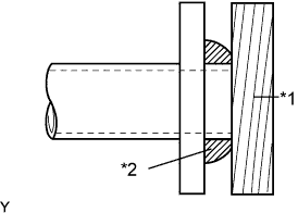
Using a plastic hammer and a wooden block, tap in a new exhaust pipe gasket until its surface is flush with the exhaust manifold.
Text in Illustration *1 Wooden Block *2 Gasket - NOTICE:
- Install the exhaust pipe gasket in the correct direction.
- Do not damage the outer surface of the exhaust pipe gasket.
- Do not reuse the exhaust pipe gasket.
- Do not push in the gasket with the exhaust pipe when installing.
 |
Install the front exhaust pipe assembly with the 2 compression springs and 2 bolts.
- Torque:
- 43 N*m{439 kgf*cm, 32 ft.*lbf}
| 26. CONNECT WIRE HARNESS |
Connect the wire harness with the 2 bolts.
- Torque:
- 13 N*m{133 kgf*cm, 10 ft.*lbf}
| 27. INSTALL NO. 1 WATER BY-PASS HOSE |
Install No. 1 water by-pass pipe with the bolt.
- Torque:
- 9.0 N*m{92 kgf*cm, 80 in.*lbf}
| 28. CONNECT HEATER WATER HOSE INLET A |
Connect heater water inlet hose A.
| 29. CONNECT HEATED OXYGEN SENSOR CONNECTOR |
Connect the heated oxygen sensor connector.
Install the sensor bracket with the bolt.
| 30. CONNECT ENGINE COOLANT TEMPERATURE SENSOR CONNECTOR |
Connect the engine coolant temperature sensor connector.
| 31. CONNECT CAMSHAFT POSITION SENSOR CONNECTOR |
Connect the camshaft position sensor connector.
| 32. CONNECT BOOSTER VACUUM TUBE |
Connect the booster vacuum tube.
| 33. CONNECT FUEL TUBE SUB-ASSEMBLY |
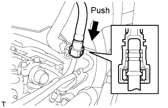 |
Insert the fuel tube connector into the fuel delivery pipe until a click sound can be heard.
- NOTICE:
- Check that there are no scratches or foreign matter around the disconnected parts of the fuel tube connector and pipe before performing this work.
- After connecting the fuel tube, check that the fuel tube connector and pipe are securely connected by pulling them.
Install the fuel pipe clamp.
 |
| 34. INSTALL OIL LEVEL DIPSTICK GUIDE |
Apply engine oil to a new O-ring.
Install the oil level dipstick guide with the bolt through a new O-ring.
- Torque:
- 10 N*m{102 kgf*cm, 7 ft.*lbf}
Install the wire harness.
| 35. INSTALL INTAKE MANIFOLD |
Install a new gasket onto the intake manifold.
Install the intake manifold with the 3 bolts and 2 nuts.
- Torque:
- 30 N*m{306 kgf*cm, 22 ft.*lbf}
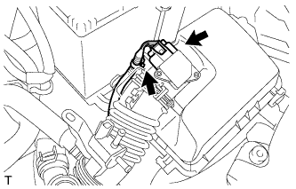
Connect the 3 wire harness clamps shown in the illustration.
| 36. INSTALL OIL LEVEL DIPSTICK SUB-ASSEMBLY |
| 37. CONNECT UNION TO CONNECTOR TUBE HOSE |
Connect the union to connector tube hose.
| 38. CONNECT VENTILATION HOSE |
Connect the ventilation hose.
| 39. CONNECT THROTTLE WITH MOTOR BODY CONNECTOR |
Install the throttle with motor body connector bracket with the nut.
- Torque:
- 9.0 N*m{92 kgf*cm, 80 in.*lbf}
Connect the throttle with motor body connector.
Connect the wire harness clamp.
| 40. CONNECT WATER BY-PASS HOSE |
Connect the water by-pass hose.
| 41. CONNECT NO. 2 WATER BY-PASS HOSE |
Connect No. 2 water by-pass hose.
| 42. INSTALL WATER FILLER SUB-ASSEMBLY |
Install the water filler sub-assembly with the 2 nuts.
- Torque:
- 7.5 N*m{76 kgf*cm, 66 in.*lbf}
Connect No. 1 radiator hose to the cylinder head.
| 43. CONNECT RESERVE TANK HOSE |
Connect the reserve tank hose.
| 44. CONNECT NO. 3 RADIATOR HOSE |
Connect No. 3 radiator hose.
| 45. INSTALL NO. 1 AIR CLEANER CAP SUB-ASSEMBLY WITH AIR CLEANER HOSE |
 |
Install air cleaner cap sub-assembly with air cleaner hose No. 1.
Tighten the hose clamp to the specified torque.
- Torque:
- 3.0 N*m{31 kgf*cm, 27 in.*lbf}
Connect the wire harness clamp and mass air flow meter connector.
 |
Connect ventilation hose No. 2.
 |
Connect the vacuum switching valve assembly connector and wire harness clamp.
 |
Connect fuel vapor feed hose No. 1 and fuel vapor feed hose No. 2 to the vacuum switching valve assembly.
| 46. INSTALL BATTERY TRAY |
| 47. INSTALL BATTERY |
| 48. ADD ENGINE OIL |
Add fresh oil and install the oil filler cap.
- Engine oil:
Oil Grade Oil Viscosity (SAE) ILSAC multigrade engine oil 5W-30
- Oil capacity:
Item Capacity Drain and refill with oil filter change 3.7 liters (3.9 US qts, 3.3 lmp. qts) Drain and refill without oil filter change 3.4 liters (3.6 US qts, 3.0 lmp. qts) Dry fill 4.1 liters (4.3 US qts, 3.6 lmp. qts)
| 49. ADD ENGINE COOLANT |
Tighten all the plugs.
Pour engine coolant into the radiator assembly until it overflows.
- Capacity:
- M/T 4.8 liters (5.1 USqts, 4.5 lmp. qts)
- A/T 4.7 liters (5.0 USqts, 4.4 lmp. qts)
- NOTICE:
- Do not substitute water for engine coolant.
- HINT:
- Use of improper engine coolant may damage the engine coolant system.
- Use only Toyota Super Long Life Coolant or similar high quality ethylene glycol based non-silicate, non-amine, non-nitrite, and non-borate engine coolant with long-life hybrid organic acid technology (coolant with long-life hybrid organic acid technology consists of a combination of low phosphates and organic acids).
Check the engine coolant level inside the radiator assembly by squeezing the inlet and outlet radiator hoses several times by hand. If the engine coolant level goes down, add engine coolant.
Install the radiator cap sub-assembly securely.
Slowly pour engine coolant into the radiator reservoir until it reaches the FULL line.
Bleed air from the cooling system.
Warm up the engine until the thermostat opens. While the thermostat is open, circulate the coolant for several minutes.
- HINT:
- The thermostat open timing can be confirmed by pressing the No. 2 radiator hose by hand, and checking when when the coolant starts to flow inside the hose.
Maintain the engine speed at 2,000 to 2,500 rpm and warm up the engine until the cooling fan operates.
Press the No. 2 radiator hose and No. 3 radiator hose several times by hand to bleed air.
- NOTICE:
- When pressing the radiator houses
- Wear protective glove.
- Be careful as the radiator hoses are hot.
- Keep your hands away form the radiator fan.
Stop the engine and wait until the coolant cools down.
If the engine coolant level is below the full level, perform steps (b) through (g) again and repeat the operation until the engine coolant level stays at the full level.
Recheck the engine coolant level inside the radiator reservoir tank assembly. If it is below the full level, add engine coolant.
| 50. INSPECT ENGINE OIL LEVEL |
Warm up the engine, then stop the engine and wait for 5 minutes.
Check that the engine oil level is between the low and full marks on the engine oil level dipstick.
If the engine oil level is low, check for oil leakage and add engine oil up to the full level mark.- NOTICE:
- Do not add engine oil to above the full level mark.
| 51. INSPECT FOR ENGINE OIL LEAK |
| 52. INSPECT FOR ENGINE COOLANT LEAK |
- CAUTION:
- To avoid the danger of being burned, do not remove the water filler cap sub-assembly while the engine and radiator assembly are still hot. Thermal expansion will cause hot engine coolant and steam to blow out from the radiator assembly.
Fill the radiator assembly with engine coolant, and attach a radiator cap tester.
 |
Pump the tester to 118 kPa (1.2 kgf/cm2, 17.1 psi), and then check that the pressure does not drop.
If the pressure drops, check the hoses, radiator assembly and water pump assembly for leaks. If there are no signs or traces of external engine coolant leaks, check the heater core, cylinder block and head.
| 53. INSPECT FOR EXHAUST GAS LEAK |
| 54. INSPECT FOR FUEL LEAK |
When using the Techstream.
Connect the Techstream to the DLC3.
Turn the ignition switch to ON and turn the tester ON.
- NOTICE:
- Do not start the engine.
Select the following menu items: Powertrain / Engine and ECT / Active Test / Control the Fuel Pump / Speed.
- HINT:
- Refer to the Techstream operator's manual for further details.
Check that there is no fuel leakage anywhere on the fuel system after doing maintenance.
| 55. INSTALL NO. 2 CYLINDER HEAD COVER |
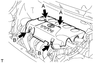 |
Tighten the 2 A nuts, then the 2 B nuts.
- Torque:
- 7.0 N*m{71 kgf*cm, 62 in.*lbf}
| 56. INSTALL ENGINE UNDER COVER RH |
| 57. INSTALL FRONT WHEEL RH |
| 58. INSTALL COWL TOP PANEL OUTER |
Install the cowl top panel outer with the 8 bolts.
- Torque:
- 6.5 N*m{66 kgf*cm, 58 in.*lbf}
Install the cowl top to cowl inner brace with the 2 bolts.
- Torque:
- 6.5 N*m{66 kgf*cm, 58 in.*lbf}
Connect the wire harness clamp.
| 59. INSTALL FRONT AIR SHUTTER SEAL RH |
Engage the 3 claws to install the front air shutter seal RH.
| 60. INSTALL FRONT WIPER MOTOR AND LINK |
Connect the connector.
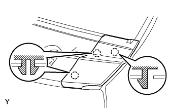
 |
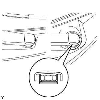
Slide the wiper link as shown in the illustration and engage the rubber pin with the body.
Install the front wiper motor and link with the 2 bolts.
- Torque:
- 5.5 N*m{56 kgf*cm, 49 in.*lbf}
| 61. INSTALL COWL TOP VENTILATOR LOUVER SUB-ASSEMBLY |
Connect the washer hoses.
 |
Engage the 5 hooks.
Engage the 8 hooks and the 4 claws.
 |
Install the cowl top ventilator louver sub-assembly with the 3 clips.
| 62. INSTALL COWL SIDE VENTILATOR SUB-ASSEMBLY LH |
Engage the 3 claws and install the cowl side ventilator sub-assembly LH.
 |
| 63. INSTALL COWL SIDE VENTILATOR SUB-ASSEMBLY RH |
- HINT:
- Use the same procedure as for the LH side.
| 64. INSTALL FRONT WIPER ARM AND BLADE ASSEMBLY LH |
Scrape any metal powder off the serrated part of the wiper arm with a round file or the equivalent (when reinstalling).
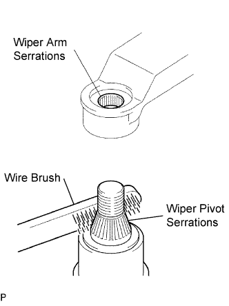 |
Clean the wiper pivot serrations with a wire brush.
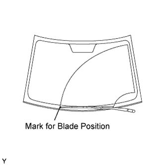
Operate the wiper, then stop the windshield wiper motor in the automatic stop position.
Align the blade tip with the mark on the windshield glass, as shown in the illustration.
 |
Tighten the nut of the front wiper arm.
- Torque:
- 26 N*m{265 kgf*cm, 19 ft.*lbf}
| 65. INSTALL FRONT WIPER ARM AND BLADE ASSEMBLY RH |
Scrape any metal powder off the serrated part of the wiper arm with a round file or the equivalent (when reinstalling).
|
Clean the wiper pivot serrations with a wire brush.
Operate the wiper, then stop the windshield wiper motor in the automatic stop position.
Align the blade tip with the mark on the windshield glass, as shown in the illustration.
 |
Tighten the nut of the front wiper arm.
- Torque:
- 26 N*m{265 kgf*cm, 19 ft.*lbf}
| 66. INSTALL FRONT WIPER ARM HEAD CAP |
Engage the claw and install the 2 front wiper arm head caps.
 |