Camshaft (For Hatchback) -- Inspection |
| 1. INSPECT CAMSHAFT TIMING GEAR ASSEMBLY |
Check the lock of camshaft timing gear.
Clamp the camshaft in a vise, and check that the camshaft timing gear is locked.
- NOTICE:
- Do not damage the camshaft.
Release the lock pin.
Text in Illustration *1 Rubber Piece *2 Vinyl Tape *a Advance Side Path *b Retard Side Path *c Open *d Close Cover the 4 oil paths of the cam journal with tape as shown in the illustration.
- HINT:
- One of the 2 grooves located on the cam journal is for retarding cam timing (upper) and the other is for advancing cam timing (lower). Each groove has 2 oil paths. Plug one of the oil paths for each groove with a piece of rubber before wrapping the cam journal with the tape.
Puncture the tape covering the advance oil path and the retard oil path on the opposite side from the advance oil path.
Apply air at about 150 kPa (1.5 kgf/cm2) pressure into the 2 broken paths (the advance side path and the retard side path).
Text in Illustration *a Advance Side Path *b Retard Side Path - NOTICE:
- Cover the paths with a piece of cloth to prevent oil splashes.
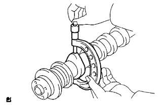
Confirm that the camshaft timing gear assembly revolves in the timing advance direction when the air pressure on the timing retard path is reduced.
Text in Illustration *a Retard Side Path *b Advance Side Path *c Decompress *d Hold Pressure - HINT:
- The lock pin is released and the camshaft timing gear revolves in the advance direction.
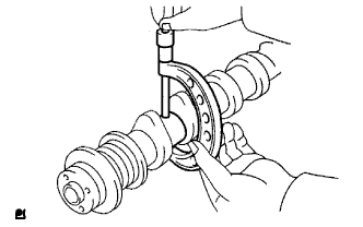
When the camshaft timing gear reaches the most advanced position, release the air pressure on the timing retard side path, and then release the air pressure on the timing advance side path.
- NOTICE:
- Camshaft timing gear assembly occasionally shifts to the retard side abruptly if the air pressure on the advance side path is released first. This often results in breakage of the lock pin.


 |
Check the revolution.
Rotate the valve timing assembly back and forth several times, except where the lock pin meets it at the most retarded angle. Check the movable range and that it rotates smoothly.
- Standard:
- Smooth movable range is about 22.5°
- NOTICE:
- Perform this check by hand, instead of using air pressure.
Check the lock in the most retarded position.
Confirm that the camshaft timing gear assembly is locked in the most retarded position.
| 2. INSPECT CAMSHAFT |
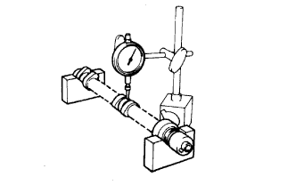 |
Inspect the camshaft for runout.
Place the camshaft on V-blocks.
Using a dial indicator, measure the circle runout at the center journal.
- Maximum circle runout:
- 0.03 mm (0.0012 in.)
Inspect the cam lobes.
Using a micrometer, measure the cam lobe height.
- Standard cam lobe height:
- 44.617 to 44.717 mm (1.7566 to 1.7605 in.)
- Minimum cam lobe height:
- 43.16 mm (1.66962 in.)
 |
Inspect the camshaft journals.
Using a micrometer, measure the journal diameter.
- Standard journal diameter:
Journal Specified Condition No. 1 journal 34.449 to 34.465 mm
(1.3563 to 1.3569 in.)Other journals 22.959 to 22.975 mm
(0.9038 to 0.9045 in.)
 |
| 3. INSPECT NO. 2 CAMSHAFT |
Inspect the camshaft for runout.
Place the camshaft on V-blocks.
Using a dial indicator, measure the circle runout at the center journal.
- Maximum circle runout:
- 0.03 mm (0.0012 in.)
Inspect the cam lobes.
Using a micrometer, measure the cam lobe height.
- Standard cam lobe height:
- 44.666 to 44.766 (1.7585 to 1.7624 in.)
- Minimum cam lobe height:
- 44.52 mm (1.7528 in.)
Inspect the camshaft journals.
Using a micrometer, measure the journal diameter.
- Standard journal diameter:
Journal Specified Condition No. 1 journal 34.449 to 34.465 mm
(1.3563 to 1.3569 in.)Other journals 22.959 to 22.975 mm
(0.9038 to 0.9045 in.)