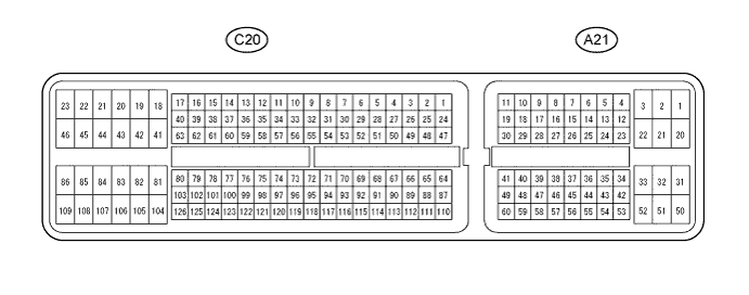
Symbol (Terminal No.)
| Wiring Color
| Terminal Description
| Condition
| Specified Condition
|
BATT (A21-20) - E1 (C20-104)
| Y - W
| Battery (for measuring battery voltage and for ECM memory)
| Always
| 11 to 14 V
|
+BM (A21-3) - ME01 (C20-43)
| GR - BR
| Power source of throttle actuator
| Always
| 11 to 14 V
|
IGSW (A21-28) - E1 (C20-104)
| R - W
| Ignition switch
| Ignition switch ON
| 11 to 14 V
|
+B (A21-2) - E1 (C20-104)
| B - W
| Power source of ECM
| Ignition switch ON
| 11 to 14 V
|
+B2 (A21-1) - E1 (C20-104)
| B - W
| Power source of ECM
| Ignition switch ON
| 11 to 14 V
|
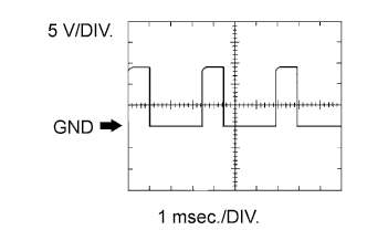
OC1+ (C20-100) - OC1- (C20-123)
| BR - R
| Camshaft timing oil control valve (OCV)
| Idling
| Pulse generation (See waveform 1)
|
MREL (A21-44) - E1 (C20-104)
| GR - W
| EFI relay
| Ignition switch ON
| 11 to 14 V
|
VG (C20-118) - E2G (C20-116)
| GR - LG
| Mass air flow meter
| Idling, Transmission gear neutral, A/C switch OFF
| 0.5 to 3.0 V
|
THA (C20-65) - ETHA (C20-88)
| P - BE
| Intake air temperature sensor
| Idling, Intake air temperature 20°C (68°F)
| 0.5 to 3.4 V
|
THW (C20-97) - ETHW (C20-96)
| L - P
| Engine coolant temperature sensor
| Idling, Engine coolant temperature 80°C (176°F)
| 0.2 to 1.0 V
|
VCTA (C20-67) - ETA (C20-91)
| W - V
| Power source of throttle position sensor (specific voltage)
| Ignition switch ON
| 4.5 to 5.5 V
|
VTA1 (C20-115) - ETA (C20-91)
| Y - V
| Throttle position sensor (for engine control)
| Ignition switch ON,
Throttle valve fully closed
| 0.5 to 1.1 V
|
Ignition switch ON,
Throttle valve fully open
| 3.2 to 4.8 V
|
VTA2 (C20-114) - ETA (C20-91)
| GR - V
| Throttle position sensor (for sensor malfunction detection)
| Ignition switch ON,
Throttle valve fully closed
| 2.1 to 3.1 V
|
Ignition switch ON,
Throttle valve fully open
| 4.6 to 5.0 V
|
VPA (A21-55) - EPA (A21-59)
| R - G
| Accelerator pedal position sensor (for engine control)
| Ignition switch ON,
Accelerator pedal released
| 0.5 to 1.1 V
|
Ignition switch ON,
Accelerator pedal fully depressed
| 2.6 to 4.5 V
|
VPA2 (A21-56) - EPA2 (A21-60)
| L - BR
| Accelerator pedal position sensor (for sensor malfunctioning detection)
| Ignition switch ON,
Accelerator pedal released
| 1.2 to 2.0 V
|
Ignition switch ON,
Accelerator pedal fully depressed
| 3.4 to 4.7 V
|
VCPA (A21-57) - EPA (A21-59)
| B - G
| Power source of accelerator pedal position sensor (for VPA)
| Ignition switch ON
| 4.5 to 5.5 V
|
VCP2 (A21-58) - EPA2 (A21-60)
| W - BR
| Power source of accelerator pedal position sensor (for VPA2)
| Ignition switch ON
| 4.5 to 5.5 V
|
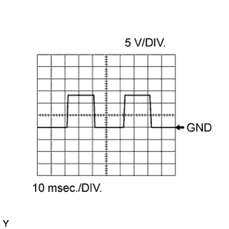
HA1A (C20-109) - E04 (C20-46)
| G - W-B
| A/F sensor heater
| Idling with warm engine
| Pulse generation (See waveform 2)
|
Ignition switch ON
| 11 to 14 V
|
A1A+ (C20-112) - E1 (C20-104)
| V -W
| A/F sensor
| Ignition switch ON
| 3.3 V*
|
A1A- (C20-113) - E1 (C20-104)
| LG - W
| A/F sensor
| Ignition switch ON
| 2.9 V*
|
HT1B (C20-47) - E03 (C20-86)
| LG - W-B
| Heated oxygen sensor heater
| Idling
| Below 3.0 V
|
Ignition switch ON
| 11 to 14 V
|
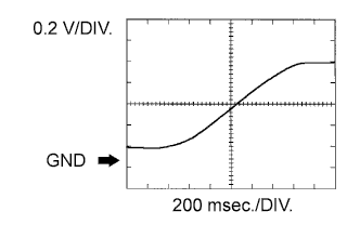
OX1B (C20-64) - EX1B (C20-87)
| G - GR
| Heated oxygen sensor
| Engine speed maintained at 2500 rpm for 2 minutes after warming up sensor
| Pulse generation (See waveform 3)
|
#10 (C20-108) - E01 (C20-45)
#20 (C20-107) - E01 (C20-45)
#30 (C20-106) - E01 (C20-45)
#40 (C20-105) - E01 (C20-45)
| SB - BR
GR - BR
P - BR
L - BR
| Fuel injector
| Ignition switch ON
| 11 to 14 V
|
Idling
| Pulse generation (See waveform 4)
|
KNK1 (C20-110) - EKNK (C20-111)
| R - G
| Knock sensor
| Engine speed maintained at 4000 after warming up engine
| Pulse generation (See waveform 5)
|
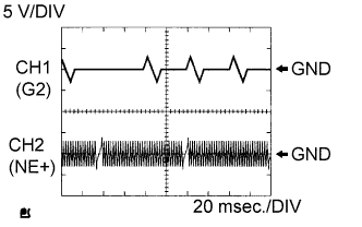
G2+ (C20-99) - NE- (C20-121)
| B - P
| Camshaft position sensor
| Idling
| Pulse generation (See waveform 6)
|
NE+ (C20-122) - NE- (C20-121)
| L - P
| Crankshaft position sensor
| Idling
| Pulse generation (See waveform 6)
|
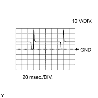
IGT1 (C20-85) - E1 (C20-104)
IGT2 (C20-84) - E1 (C20-104)
IGT3 (C20-83) - E1 (C20-104)
IGT4 (C20-82) - E1 (C20-104)
| W - W
BE - W
G - W
LG - W
| Ignition coil (ignition signal)
| Idling
| Pulse generation (See waveform 7)
|
IGF1 (C20-81) - E1 (C20-104)
| Y - W
| Ignition coil (ignition confirmation signal)
| Ignition switch ON
| 4.5 to 5.5 V
|
Idling
| Pulse generation (See waveform 7)
|
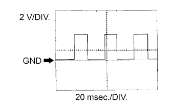
PRG (C20-49) - E01 (C20-45)
| L - BR
| Purge VSV
| Ignition switch ON
| 11 to 14 V
|
Idling, during purge control
| Pulse generation (See waveform 8)
|
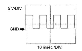
SPD (A21-8) - E1 (C20-104)
| V - W
| Speed signal from combination meter
| Driving at 20 km/h (12 mph)
| Pulse generation (See waveform 9)
|
STA (A21-48) - E1 (C20-104)
| BR - W
| Starter signal
| Cranking
| 11 to 14 V
|
STAR (C20-52) - E1 (C20-104)
| BE - W
| Starter relay control
| Ignition switch ON, Shift position P or N (for A/T), Clutch pedal fully depressed (for M/T)
| Below 1.5 V
|
Cranking
| 6.0 V or more
|
ACCR (A21-13) - E01 (C20-45)
| G - BR
| ACC (Accessory) Cut relay control signal
| Cranking
| Below 1.5 V
|
STSW (A21-14) - E1 (C20-104)
| B - W
| Ignition switch signal
| Ignition switch START position
| 6.0 V or more
|
STP (A21-36) - E1 (C20-104)
| G - W
| Stop light switch
| Brake pedal depressed
| 7.5 to 14 V
|
Brake pedal released
| Below 1.5 V
|
ST1- (A21-35) - E1 (C20-104)
| Y - W
| Stop light switch
(opposite to STP terminal)
| Ignition switch ON,
Brake pedal depressed
| Below 1.5 V
|
Ignition switch ON,
Brake pedal released
| 7.5 to 14 V
|
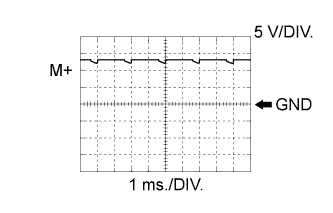
M+ (C20-42) - ME01 (C20-43)
| G - BR
| Throttle actuator
| Idling with warm engine
| Pulse generation (See waveform 10)
|
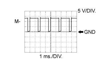
M- (C20-41) - ME01 (C20-43)
| R - BR
| Throttle actuator
| Idling with warm engine
| Pulse generation (See waveform 11)
|
FC (A21-7) - E01 (C20-45)
| V - BR
| Fuel pump control
| Ignition switch ON
| 11 to 14 V
|
Idling
| Below 1.5 V
|
W (A21-24) - E1 (C20-104)
| B - W
| MIL
| Ignition switch ON (MIL goes on)
| Below 1.5 V
|
Idling (MIL goes off)
| 11 to 14 V
|
TC (A21-27) - E1 (C20-104)
| P - W
| Terminal TC of DLC 3
| Ignition switch ON
| 11 to 14 V
|
TACH (A21-15) - E1 (C20-104)
| LG - W
| Engine speed
| Idling
| Pulse generation (See waveform 12)
|
VPMP (A21-42) - E1 (C20-104)
| P - W
| Vent valve (built into canister pump module)
| Ignition switch ON
| 11 to 14 V
|
MPMP (A21-34) - E1 (C20-104)
| V - W
| Leak detection pump (built into canister pump module)
| Leak detection pump OFF
| Below 3 V
|
Leak detection pump ON
| 11 to 14 V
|
VCPP (C20-70) - EPPM (C20-94)
| V - BE
| Power source for canister pressure sensor (specific voltage)
| Ignition switch ON
| 4.5 to 5.5 V
|
PPMP (C20-71) - EPPM (C20-94)
| L - BE
| Canister pressure sensor (built into canister pump module)
| Ignition switch ON
| 3 to 3.6 V
|
ELS (A21-31) - E1 (C20-104)
| G - W
| Electric load
| Tail light switch ON
| 7.5 to 14 V
|
Tail light switch OFF
| Below 1.5 V
|
ELS3 (A21-33) - E1 (C20-104)
| V - W
| Electric load
| Defogger switch ON
| 7.5 to 14 V
|
Defogger switch OFF
| Below 1.5 V
|
FAN (A21-21) - E1 (C20-104)
| BE - W
| Fan No. 1 relay
| Ignition switch ON
| 11 to 14 V
|
Idling with A/C ON, or high engine coolant temperature
| Below 1.5 V
|
FAN2 (A21-22) - E1 (C20-104)
| LG - W
| Fan No. 2 relay
| Idling with high engine coolant temperature
| Below 1.5 V
|
ALT (C20-50) - E1 (C20-104)
| P - W
| Generator
| Ignition switch ON
| 11 to 14 V
|
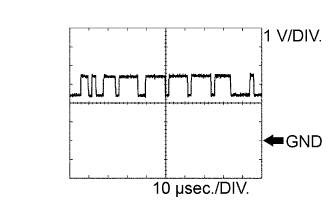
CANH (A21-41) - E1 (C20-104)
| L - W
| CAN communication line
| Ignition switch ON
| Pulse generation (See waveform 13)
|
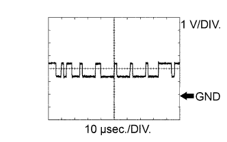
CANL (A21-49) - E1 (C20-104)
| W - W
| CAN communication line
| Ignition switch ON
| Pulse generation (See waveform 14)
|