Lighting System Automatic Light Control Sensor Circuit
DESCRIPTION
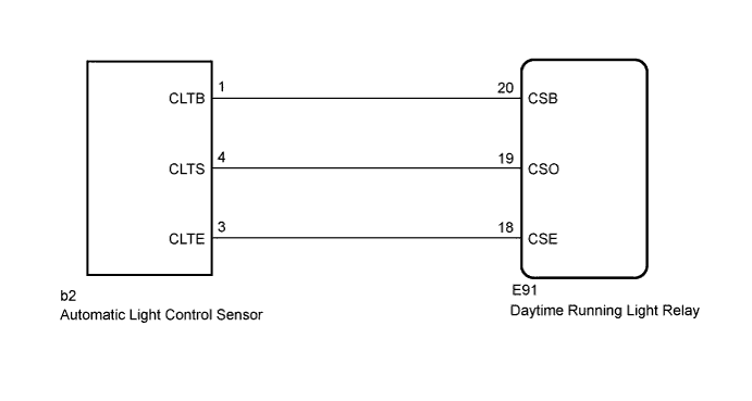
WIRING DIAGRAM
INSPECTION PROCEDURE
CHECK HARNESS AND CONNECTOR (DAYTIME RUNNING LIGHT RELAY - AUTOMATIC LIGHT CONTROL SENSOR)
INSPECT DAYTIME RUNNING LIGHT RELAY
INSPECT AUTOMATIC LIGHT CONTROL SENSOR
LIGHTING SYSTEM - Automatic Light Control Sensor Circuit |
DESCRIPTION
The daytime running light relay receives a signal from the automatic light control sensor.
WIRING DIAGRAM
INSPECTION PROCEDURE
| 1.CHECK HARNESS AND CONNECTOR (DAYTIME RUNNING LIGHT RELAY - AUTOMATIC LIGHT CONTROL SENSOR) |
Disconnect the b2 automatic light control sensor connector and E91 daytime running light relay connector.
Measure the resistance according to the value(s) in the table below.
- Standard Resistance:
Tester connection
| Condition
| Specified condition
|
b2-1 (CLTB) - E91-20 (CSB)
| Always
| Below 1 Ω
|
b2-3 (CLTE) - E91-18 (CSE)
| Always
| Below 1 Ω
|
b2-4 (CLTS) - E91-19 (CSO)
| Always
| Below 1 Ω
|
b2-1 (CLTB) - Body ground
| Always
| 10 kΩ or higher
|
b2-3 (CLTE) - Body ground
| Always
| 10 kΩ or higher
|
b2-4 (CLTS) - Body ground
| Always
| 10 kΩ or higher
|
| | REPAIR OR REPLACE HARNESS OR CONNECTOR |
|
|
| 2.INSPECT DAYTIME RUNNING LIGHT RELAY |
Reconnect the E91 daytime running light relay connector.
Measure the voltage according to the value(s) in the table below.
- Standard Voltage:
Tester connection
| Switch Condition
| Specified voltage
|
E91-20 (CSB) - E91-18 (CSE)
| Ignition switch off → ON
| Below 1 V → 11 to 14 V
|
| 3.INSPECT AUTOMATIC LIGHT CONTROL SENSOR |
Reconnect the b2 automatic light control sensor connector.
Connect an oscilloscope to the automatic light control sensor connector.
Check the waveform.
- OK:
Tester Connection
| Tool Setting
| Switch Condition
| Specified Condition
|
b2-3 (CLTE) - b2-4 (CLTS)
| 2 V/DIV., 5 ms./DIV.
| Ignition switch ON, light control switch in off
| Correct waveform is as shown
|
- HINT:
- If the ambient light becomes brighter, width A becomes narrower.