Power Window Control System Power Windows Do Not Operate At All
DESCRIPTION
WIRING DIAGRAM
INSPECTION PROCEDURE
CHECK HARNESS AND CONNECTOR (POWER WINDOW POWER SOURCE)
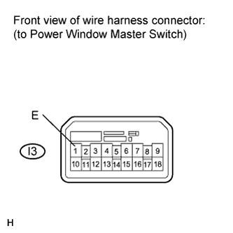
CHECK HARNESS AND CONNECTOR (POWER WINDOW MASTER SWITCH - BODY GROUND)
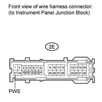
CHECK HARNESS AND CONNECTOR (MAIN BODY ECU - BODY GROUND)
POWER WINDOW CONTROL SYSTEM - Power Windows do not Operate at All |
DESCRIPTION
If none of the power windows operate, a malfunction may exist in the power window master switch, main body ECU (instrument panel junction block) or wire harness.
WIRING DIAGRAM
INSPECTION PROCEDURE
| 1.CHECK HARNESS AND CONNECTOR (POWER WINDOW POWER SOURCE) |
Disconnect the power window master switch connector.
Measure the voltage according to the value(s) table below.
- Standard Voltage:
Tester Connection
| Switch Condition
| Specified Condition
|
I3-6 (B) - Body ground
| Ignition switch ON
| 11 to 14 V
|
| 2.CHECK HARNESS AND CONNECTOR (POWER WINDOW MASTER SWITCH - BODY GROUND) |
Measure the resistance according to the value(s) in the table below.
- Standard Resistance:
Tester Connection
| Condition
| Specified Condition
|
I3-1 (E) - Body ground
| Always
| Below 1 Ω
|
| | REPAIR OR REPLACE HARNESS OR CONNECTOR |
|
|
| 3.CHECK HARNESS AND CONNECTOR (MAIN BODY ECU - BODY GROUND) |
Disconnect the instrument panel junction block connector.
Measure the resistance according to the value(s) in the table below.
- Standard Resistance:
Tester Connection
| Condition
| Specified Condition
|
2E-17 (PWS) - Body ground
| Always
| Below 1 Ω
|
| | REPAIR OR REPLACE HARNESS OR CONNECTOR |
|
|
| OK |
|
|
|
| REPLACE MAIN BODY ECU (INSTRUMENT PANEL JUNCTION BLOCK) |
|