Power Window Control System Driver Side Power Window Does Not Operate With Power Window Master Switch
DESCRIPTION
WIRING DIAGRAM
INSPECTION PROCEDURE
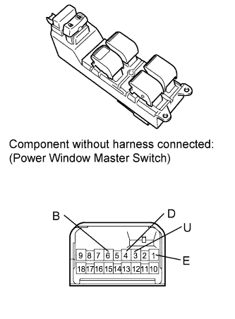
INSPECT POWER WINDOW MASTER SWITCH (DRIVER SWITCH)
CHECK HARNESS AND CONNECTOR (MASTER SWITCH - MOTOR (DRIVER SIDE))
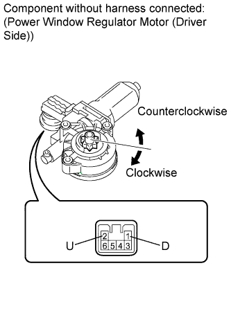
INSPECT POWER WINDOW REGULATOR MOTOR ASSEMBLY (DRIVER SIDE)
POWER WINDOW CONTROL SYSTEM - Driver Side Power Window does not Operate with Power Window Master Switch |
DESCRIPTION
If the manual UP or DOWN and AUTO DOWN functions do not operate, a malfunction may exist in the power window master switch, power window regulator motor or wire harness.
WIRING DIAGRAM
INSPECTION PROCEDURE
| 1.INSPECT POWER WINDOW MASTER SWITCH (DRIVER SWITCH) |
Remove the power window master switch (COROLLA_ZRE142 RM000002AC90CLX.html).
Measure the resistance according to the value(s) in the table below.
- Standard Resistance:
Tester Connection
| Switch Condition
| Specified Condition
|
1 (E) - 4 (D)
3 (U) - 6 (B)
| UP
| Below 1 Ω
|
1 (E) - 3 (U)
1 (E) - 4 (D)
| OFF
| Below 1 Ω
|
1 (E) - 3 (U)
6 (B) - 4 (D)
| DOWN
| Below 1 Ω
|
1 (E) - 3 (U)
6 (B) - 4 (D)
| AUTO DOWN
| Below 1 Ω
|
| 2.CHECK HARNESS AND CONNECTOR (MASTER SWITCH - MOTOR (DRIVER SIDE)) |
Disconnect the power window regulator motor assembly (driver side) motor connector.
Measure the resistance according to the value(s) in the table below.
- Standard Resistance:
Tester Connection
| Condition
| Specified Condition
|
I3-4 (D) - I7-1 (D)
| Always
| Below 1 Ω
|
I3-3 (U) - I7-2 (U)
| Always
| Below 1 Ω
|
I3-4 (D) - Body ground
| Always
| 10 kΩ or higher
|
I3-3 (U) - Body ground
| Always
| 10 kΩ or higher
|
| | REPAIR OR REPLACE HARNESS OR CONNECTOR |
|
|
| 3.INSPECT POWER WINDOW REGULATOR MOTOR ASSEMBLY (DRIVER SIDE) |
Remove the power window regulator motor assembly (COROLLA_ZRE142 RM000002YF201SX.html).
Check power window regulator motor operation:
Apply battery voltage to connector terminals 1 and 2.
- NOTICE:
- Do not apply battery voltage to any terminals except terminals 1 and 2.
Check that the motor gear rotates smoothly as follows.
- OK:
Measurement Condition
| Specified Condition
|
Battery positive (+) → 1 (D)
Battery negative (-) → 2 (U)
| Motor gear rotates counterclockwise
|
Battery positive (+) → 2 (U)
Battery negative (-) → 1 (D)
| Motor gear rotates clockwise
|
Check PTC operation:
- NOTICE:
- This check must be performed with the power window regulator and door glass installed on the vehicle.
Install the power window regulator motor (COROLLA_ZRE142 RM000002YF001UX.html).
Connect an electrical tester DC 400 A probe to the wire harness of terminal 2.
- NOTICE:
- Match the arrow mark of the probe with the direction of the current flow.
Fully close the door glass by pulling up the power window switch. Wait for approximately 60 seconds.
Continue to pull up the power window switch and measure how long it takes for the electrical current to change from a range of 16 to 28 A to approximately 1 A (current shut-off inspection).
- Standard:
- 4 to 90 seconds
Wait for 60 seconds after the previous step, and then push down press the power window switch (driver side).
- OK:
- The driver side window goes down.