REMOVE CENTER INSTRUMENT CLUSTER FINISH PANEL SUB-ASSEMBLY (w/ USB Audio System)
REMOVE RADIO RECEIVER WITH BRACKET (for Radio Receiver Type without USB Audio System)
REMOVE RADIO RECEIVER WITH BRACKET (for Radio Receiver Type with USB Audio System)
REMOVE RADIO AND DISPLAY RECEIVER WITH BRACKET (for Radio and Display Type)
REMOVE NAVIGATION RECEIVER WITH BRACKET (for Navigation Receiver Type)
REMOVE SHIFT LEVER KNOB SUB-ASSEMBLY (for Automatic Transaxle)
REMOVE CENTER NO. 1 INSTRUMENT CLUSTER FINISH PANEL ASSEMBLY (for Manual Transaxle)
REMOVE CENTER NO. 1 INSTRUMENT CLUSTER FINISH PANEL ASSEMBLY (for Automatic Transaxle)
REMOVE AIR CONDITIONING PANEL ASSEMBLY (for Manual Air Conditioning System)
REMOVE AIR CONDITIONING CONTROL ASSEMBLY (for Automatic Air Conditioning System)
REMOVE NO. 2 INSTRUMENT PANEL UNDER COVER SUB-ASSEMBLY (w/ Instrument Panel Under Cover)
Lower Instrument Panel -- Removal |
| 1. PRECAUTION |
| 2. DISCONNECT CABLE FROM NEGATIVE BATTERY TERMINAL |
- CAUTION:
- Wait at least 90 seconds after disconnecting the cable from the negative (-) battery terminal to disable the SRS system.
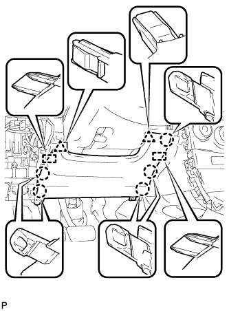
| 3. REMOVE LOWER INSTRUMENT PANEL FINISH PANEL LH |
Disengage the 3 claws and clip, and then remove the lower instrument panel finish panel LH.
 |
| 4. REMOVE LOWER INSTRUMENT PANEL FINISH PANEL RH |
Disengage the 3 claws and clip, and then remove the lower instrument panel finish panel RH.
 |
| 5. REMOVE INSTRUMENT PANEL FINISH PANEL END LH |
Apply protective tape to the area shown in the illustration.
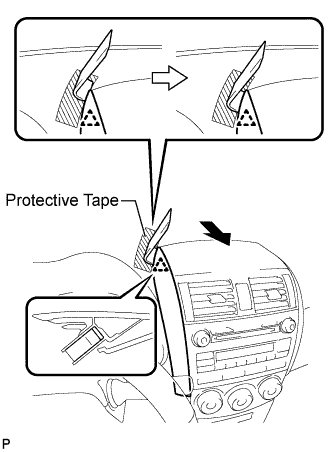 |
Insert a roof moulding remover and slide it toward the clip.
Pull the remover with both hands to disengage the clip as shown in the illustration.
Disengage the 2 claws and clip, and remove the instrument panel finish panel end LH.
 |
| 6. REMOVE INSTRUMENT PANEL FINISH PANEL END RH |
Apply protective tape to the area shown in the illustration.
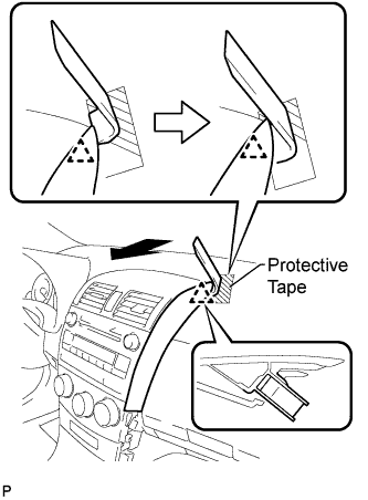 |
Insert a roof moulding remover and slide it toward the clip.
Pull the remover with both hands to disengage the clip as shown in the illustration.
Disengage the 2 claws and clip, and remove the instrument panel finish panel end RH.
 |
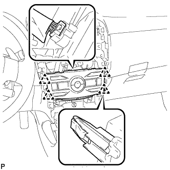
| 7. REMOVE CENTER INSTRUMENT PANEL REGISTER ASSEMBLY |
Disengage the 2 claws, 4 clips, and 2 guides.
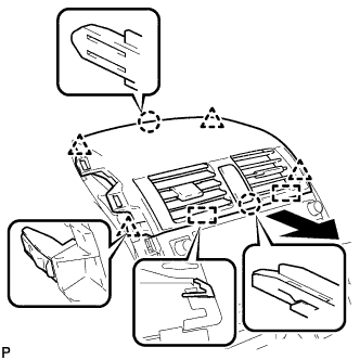 |
w/o Daytime Running Light:
Disengage the clamp.
Disconnect each connector and remove the center instrument panel register assembly.
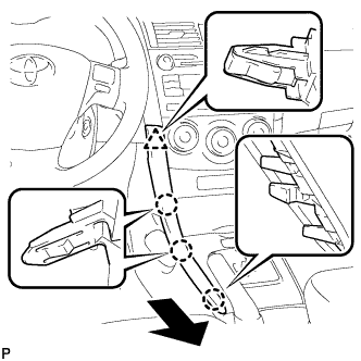
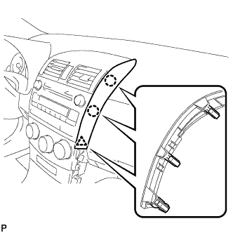
| 8. REMOVE INSTRUMENT CLUSTER FINISH PANEL ASSEMBLY |
Operate the tilt lever to lower the steering wheel assembly.
Apply protective tape to the area shown in the illustration.
 |
Disengage the guide, claw and 3 clips, and then remove the instrument cluster finish panel assembly.
 |
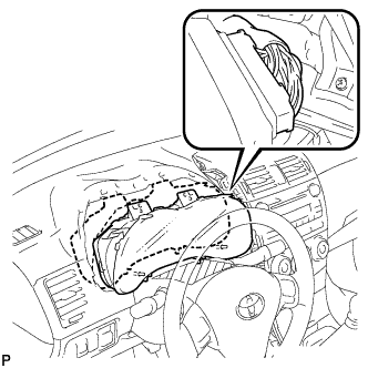
| 9. REMOVE COMBINATION METER ASSEMBLY |
Remove the 2 screws.
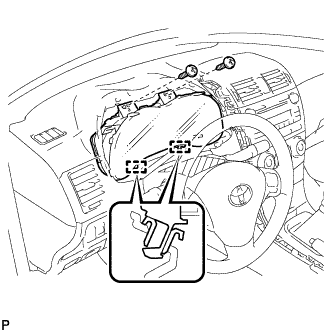 |
Disengage the 2 guides.
- NOTICE:
- When removing the combination meter assembly, be careful not to break the guide.
Pull the combination meter assembly, disconnect the connector, and remove the combination meter assembly.
- NOTICE:
- When removing the combination meter assembly, do not damage the upper instrument panel sub-assembly or combination meter assembly.
 |
| 10. REMOVE FRONT PILLAR GARNISH LH |
Pull the upper part of the garnish toward the inside of the cabin and disengage the garnish from the base of 2 clips.
- HINT:
- Make the front pillar garnish LH hang down from the front pillar garnish clip.
 |
Turn the end of the front pillar garnish clip 90° with needle-nosed pliers and remove it from the front pillar garnish LH.
- NOTICE:
- Front pillar garnish clips are reusable if they are not removed from the vehicle and have no damage.
- Replace the front pillar garnish clips with new ones if they are removed from the vehicle.
- HINT:
- Tape the tips of the needle-nosed pliers before use.
 |
Disengage the 2 guides at the front end of the front pillar garnish LH and remove it.
Protect the curtain shield airbag assembly.
Cover the airbag with a 700 mm (27.56 in.) x 120 mm (4.72 in.) cloth or piece of nylon and secure the ends of the cover with tape, as shown in the illustration.
- NOTICE:
- Cover the curtain shield airbag with a protective cover as soon as the front pillar garnish is removed.
 |
| 11. REMOVE FRONT PILLAR GARNISH RH |
- HINT:
- Use the same procedure as for the LH side.
| 12. REMOVE LOWER INSTRUMENT PANEL FINISH PANEL ASSEMBLY |
Disengage the 6 claws and 3 clips.
 |
Disconnect each connector and remove the lower instrument panel finish panel assembly.
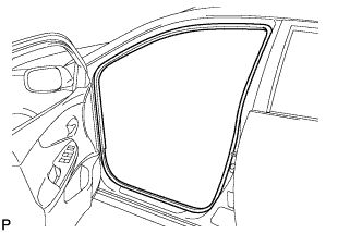
| 13. DISCONNECT FRONT DOOR OPENING TRIM WEATHERSTRIP LH |
Remove the front door opening trim weatherstrip LH.
 |
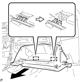
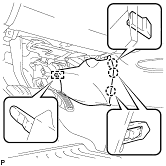
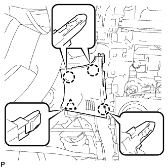
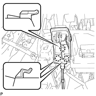
| 14. REMOVE GLOVE COMPARTMENT DOOR ASSEMBLY |
Disengage the claw and release the glove compartment door stopper.
 |
Bend portions (A) and (B) in the direction indicated by the arrows in the illustration to release the 2 stoppers, and lower the glove compartment door assembly until the front of the door is level.
Pull the glove compartment door assembly horizontally toward the rear of the vehicle to release the 2 hinges, and remove the glove compartment door assembly.
- NOTICE:
- Pulling the glove compartment door assembly upward to remove it will cause the hinges to deform. Be sure to pull out the compartment door horizontally.
 |
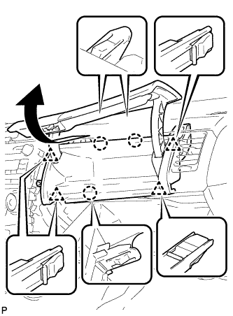
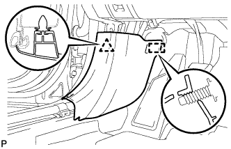
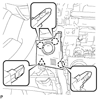
| 15. REMOVE NO. 1 INSTRUMENT PANEL BOX DOOR SUB-ASSEMBLY |
Remove the screw <B>.
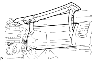 |
Disengage the 3 claws and 4 clips, and then remove the No. 1 instrument panel box door sub-assembly.
 |
| 16. DISCONNECT FRONT DOOR OPENING TRIM WEATHERSTRIP RH |
- HINT:
- Use the same procedure for the RH side and LH side.
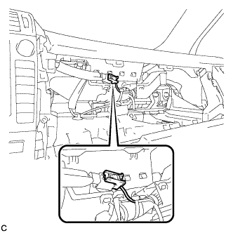
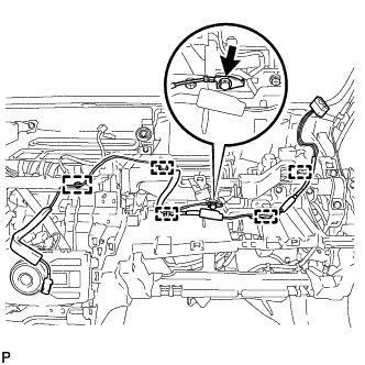
| 17. DISCONNECT INSTRUMENT PANEL WIRE ASSEMBLY |
Check that the ignition switch is off.
Check that the cable is disconnected from the negative (-) battery terminal.
- CAUTION:
- Wait at least 90 seconds after disconnecting the cable from the negative (-) battery terminal to disable the SRS system.
Disconnect the connector.
- NOTICE:
- When disconnecting the airbag connector, take care not to damage the airbag wire harness.
 |
| 18. REMOVE UPPER INSTRUMENT PANEL SUB-ASSEMBLY |
Operate the tilt lever to lower the steering wheel assembly.
Disconnect each connector.
Remove the 2 screws <B>.
Remove the passenger airbag bolt <A>.
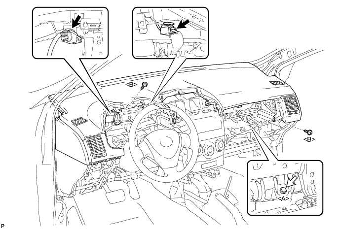
Disengage the 5 clips and 4 guides.

Disengage the 5 claws and then remove the upper instrument panel sub-assembly.

- NOTICE:
- When removing the upper instrument panel sub-assembly, be careful not to damage it or the steering wheel assembly.
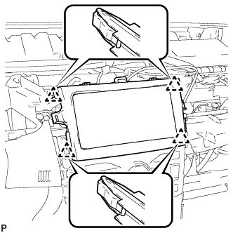
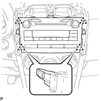
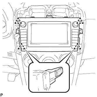
| 19. REMOVE CENTER INSTRUMENT CLUSTER FINISH PANEL SUB-ASSEMBLY (w/ USB Audio System) |
Disengage the 4 clips and remove the center instrument cluster finish panel sub-assembly.
 |
| 20. REMOVE RADIO RECEIVER WITH BRACKET (for Radio Receiver Type without USB Audio System) |
Remove the 4 bolts.
 |
Pull the radio receiver with bracket toward the rear of the vehicle and disengage the 4 clips.
 |
Disconnect each connector and remove the radio receiver with bracket.
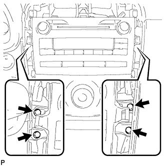
| 21. REMOVE RADIO RECEIVER WITH BRACKET (for Radio Receiver Type with USB Audio System) |
Remove the 4 bolts.
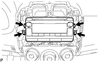 |
Disconnect each connector and remove the radio receiver with bracket.
| 22. REMOVE RADIO AND DISPLAY RECEIVER WITH BRACKET (for Radio and Display Type) |
Remove the 4 bolts.
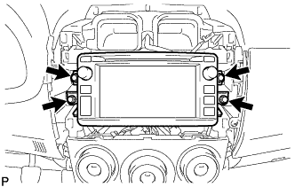 |
Disconnect each connector and remove the radio and display receiver with bracket.
| 23. REMOVE NAVIGATION RECEIVER WITH BRACKET (for Navigation Receiver Type) |
Remove the 4 bolts.
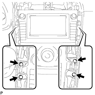 |
Pull the navigation receiver with bracket toward the rear of the vehicle and disengage the 4 clips.
 |
Disconnect each connector and remove the navigation receiver with bracket.
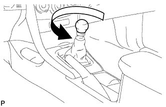
| 24. REMOVE SHIFT LEVER KNOB SUB-ASSEMBLY (for Manual Transaxle) |
Turn the shift lever knob counterclockwise and remove the shift lever knob sub-assembly.
 |
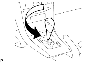
| 25. REMOVE SHIFT LEVER KNOB SUB-ASSEMBLY (for Automatic Transaxle) |
Turn the shift lever knob counterclockwise and remove the shift lever knob sub-assembly.
 |
| 26. REMOVE CENTER NO. 1 INSTRUMENT CLUSTER FINISH PANEL ASSEMBLY (for Manual Transaxle) |
Disengage the 2 claws and 2 clips.
 |
Disengage the guide and remove the center No.1 instrument cluster finish panel assembly.
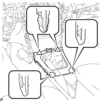
| 27. REMOVE CENTER NO. 1 INSTRUMENT CLUSTER FINISH PANEL ASSEMBLY (for Automatic Transaxle) |
Disengage the 2 claws and 2 clips.
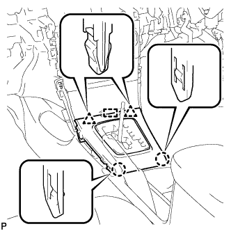 |
Disengage the guide and remove the center No.1 instrument cluster finish panel assembly.
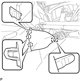
| 28. REMOVE INSTRUMENT PANEL BOX ASSEMBLY |
Remove the 2 screws <B>.
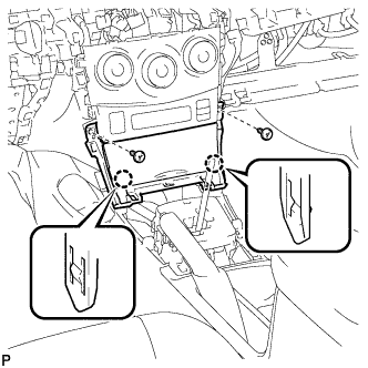 |
Disengage the 2 claws.
Disconnect the connector and remove the instrument panel box assembly.
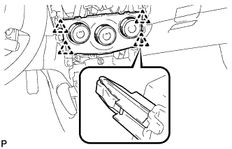
| 29. REMOVE INSTRUMENT PANEL HOLE COVER |
Disengage the 4 claws.
 |
Disconnect each connector and remove the instrument panel hole cover.
| 30. REMOVE AIR CONDITIONING PANEL ASSEMBLY (for Manual Air Conditioning System) |
Disengage the 4 clips and remove the air conditioning panel assembly.
 |
Disconnect each connector.
Disengage the 2 claws and the No. 2 heater control cable sub-assembly.
 |
Disengage the 2 claws and the airmix damper control cable sub-assembly.
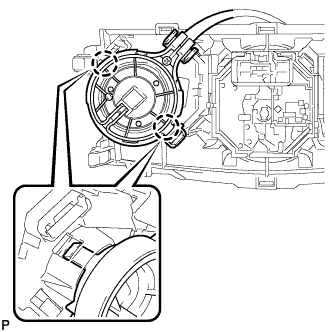 |
| 31. REMOVE AIR CONDITIONING CONTROL ASSEMBLY (for Automatic Air Conditioning System) |
Disengage the 4 clips and remove the air conditioning control assembly.
 |
Disconnect the connector.
| 32. REMOVE FRONT DOOR SCUFF PLATE LH |
Disengage the 8 claws and remove the front door scuff plate LH.
 |
| 33. REMOVE COWL SIDE TRIM BOARD LH |
Disengage the clip and guide, and remove the cowl side trim board LH.
 |
| 34. REMOVE FRONT NO. 1 CONSOLE BOX INSERT |
Disengage the 3 claws.
 |
Disengage the guide and remove the front No. 1 console box insert.
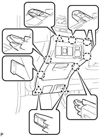
| 35. REMOVE LOWER INSTRUMENT PANEL FINISH PANEL SUB-ASSEMBLY |
Remove the 2 screws <B>.
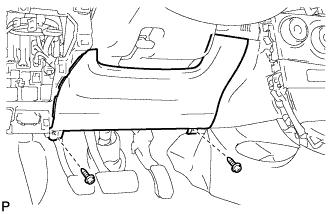 |
Disengage the 5 claws, 2 guides and 2 clips, and then remove the lower instrument panel finish panel sub-assembly.
 |
| 36. REMOVE NO. 1 SWITCH HOLE BASE (w/o Smart Key System) |
Disengage the 3 claws and clip, and then remove the No. 1 switch hole base.
 |
| 37. REMOVE NO. 1 SWITCH HOLE BASE (w/ Smart Key System) |
Disengage the 3 claws and clip.
 |
Disconnect the connector and remove the No. 1 switch hole base.
| 38. REMOVE FRONT DOOR SCUFF PLATE RH |
- HINT:
- Use the same procedure for the RH side and LH side.
| 39. REMOVE COWL SIDE TRIM BOARD RH |
- HINT:
- Use the same procedure for the RH side and LH side.
| 40. REMOVE NO. 2 INSTRUMENT PANEL UNDER COVER SUB-ASSEMBLY (w/ Instrument Panel Under Cover) |
Disengage the 3 claws.
 |
Disengage the guide and remove the No. 2 instrument panel under cover sub-assembly.
| 41. REMOVE FRONT NO. 2 CONSOLE BOX INSERT |
Disengage the 3 claws.
 |
Disengage the guide and remove the front No. 2 console box insert.
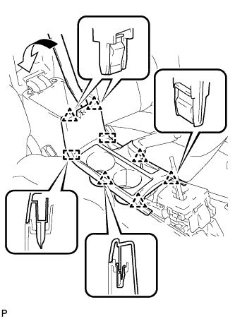
| 42. REMOVE UPPER CONSOLE PANEL SUB-ASSEMBLY |
Using a moulding remover, disengage the 6 clips and 2 guides, and remove the upper console panel sub-assembly.
 |
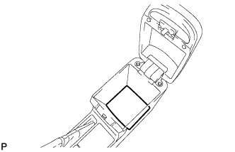
| 43. REMOVE CONSOLE BOX CARPET |
Remove the console box carpet.
 |
| 44. REMOVE CONSOLE BOX ASSEMBLY (for Manual Transaxle) |
Remove the 2 bolts.
 |
Remove the 2 screws and the console box assembly.
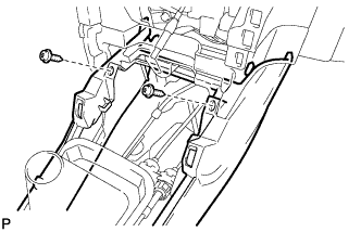 |
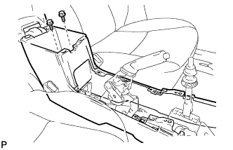
| 45. REMOVE CONSOLE BOX ASSEMBLY (for Automatic Transaxle) |
Remove the 2 bolts and 2 screws.
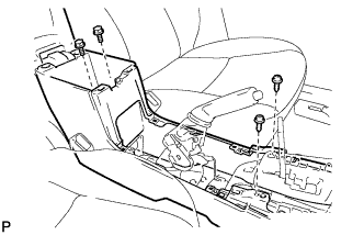 |
Remove the 2 screws and the console box assembly.
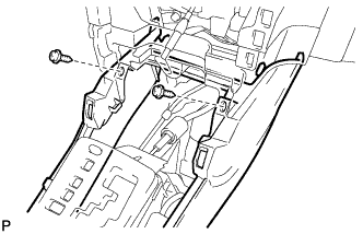 |
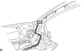
| 46. REMOVE NO. 2 ANTENNA CORD SUB-ASSEMBLY |
Disconnect the connector.
 |
Disengage the clamp.
 |
for 3 Connector Type:
Remove the bolt.
Disconnect the connector.
Disengage the 5 clamps and remove the No. 2 antenna cord sub-assembly.
for 2 Connector Type:
Remove the bolt.
Disengage the 5 clamps and remove the No. 2 antenna cord sub-assembly.
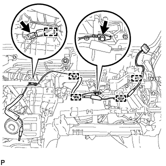
| 47. REMOVE LOWER INSTRUMENT PANEL SUB-ASSEMBLY |
Disengage the 2 claws and DLC3.
 |
Disengage the 3 claws and remove the hood lock control cable assembly.
 |
Disengage each clamp.
Disconnect each connector.
Remove the 3 screws <F>.

Remove the screw <F>.
Remove the 2 bolts <C>.
Remove the 8 screws <D> or <E>.
Disengage the 2 claws and remove the lower instrument panel sub-assembly.
