Air Conditioning Panel (For Manual Air Conditioning System) -- Inspection |
| 1. INSPECT NO. 1 HEATER CONTROL (AIR INLET CONTROL SWITCH) |
Disconnect the connector from the No. 1 heater control (air inlet control switch).
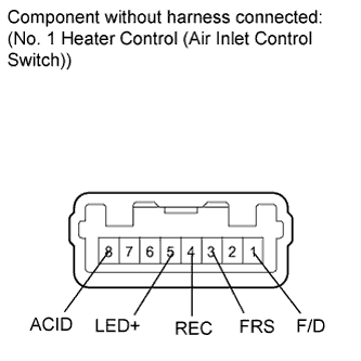 |
Measure the resistance according to the value(s) in the table below.
- Standard Resistance:
Tester Connection Switch Condition Specified Condition 3 (FRS) - 4 (REC) Air inlet control switch: FREE Below 1 Ω 3 (FRS) - 4 (REC) Air inlet control switch: LOCK 10 kΩ or higher 1 (F/D) - 8 (ACID) Mode control dial: except Foot/DEF position and DEF position 10 kΩ or higher 1 (F/D) - 8 (ACID) Mode control dial: Foot/DEF position or DEF position Below 1 Ω
Check that the indicator light comes on.
Turn the No. 1 heater control (air inlet control switch) to LOCK.
Connect a positive (+) lead from the battery to terminal 2 and a negative (-) lead from the battery to terminal 4, and check that the indicator light comes on.
- OK:
- The indicator light comes on.
Check that the illumination comes on.
Connect a positive (+) lead from the battery to terminal 7 and negative (-) to terminal 6, and check that the illumination comes on.
- OK:
- The illumination comes on.
| 2. INSPECT NO. 2 HEATER CONTROL (BLOWER SWITCH) |
Disconnect the connector from the No. 2 heater control (blower switch).
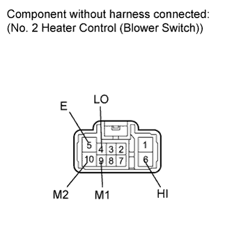 |
Measure the resistance according to the value(s) in the table below.
- Standard Resistance:
Tester Connection Switch Condition Specified Condition 4 (LO), 6 (HI), 9 (M1), 10 (M2) - 5 (E) Blower switch: OFF 10 kΩ or higher 4 (LO) - 5 (E) Blower switch: LO Below 1 Ω 4 (LO), 9 (M1) - 5 (E) Blower switch: M1 Below 1 Ω 4 (LO), 10 (M2) - 5 (E) Blower switch: M2 Below 1 Ω 4 (LO), 6 (HI) - 5 (E) Blower switch: HI Below 1 Ω
| 3. INSPECT NO. 3 HEATER CONTROL |
Disconnect the connector from the No. 3 heater control.
 |
Measure the resistance according to the value(s) in the table below.
- Standard Resistance:
Tester Connection Switch Condition Specified Condition 2 (B) - 3 (A/C) A/C switch: LOCK Below 1 Ω 2 (B) - 3 (A/C) A/C switch: FREE 10 kΩ or higher 7 (B) - 8 (E)*1 Air mix control dial: MAX HOT position Below 1 Ω 7 (B) - 8 (E)*1 Air mix control dial: except MAX HOT position 10 kΩ or higher
- HINT:
- *1: w/ PTC heater
Check that the indicator light comes on.
Connect a positive (+) lead from the battery to terminal 3 and a negative (-) lead from the battery to terminal 4, and check that the indicator light comes on.
- OK:
- The indicator light comes on.
Check that the illumination comes on.
Connect a positive (+) lead from the battery to terminal 5 and a negative (-) lead from the battery to terminal 6, and check that the illumination comes on.
- OK:
- The illumination comes on.