Condenser -- Installation |
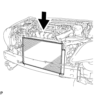
| 1. INSTALL CONDENSER ASSEMBLY WITH RECEIVER |
Install the condenser assembly with receiver as shown in the illustration.
- HINT:
- If the condenser is replaced with a new one, add compressor oil to the new condenser.
- Capacity:
- 40 cc (1.4 fl.oz.)
- Compressor oil:
- ND-8 or equivalent
 |
| 2. INSTALL NO. 2 FAN SHROUD (for 2ZR-FE) |
Engage the 2 claws and install the No. 2 fan shroud to the radiator assembly with the 2 bolts.
- Torque:
- 7.0 N*m{71 kgf*cm, 62 in.*lbf}
 |
| 3. INSTALL NO. 2 FAN SHROUD (for 2AZ-FE) |
Engage the 2 claws and install the No. 2 fan shroud to the radiator assembly with the 2 bolts.
- Torque:
- 7.0 N*m{71 kgf*cm, 62 in.*lbf}
 |
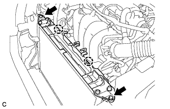
| 4. INSTALL UPPER RADIATOR SUPPORT SUB-ASSEMBLY (for 2ZR-FE) |
Install the upper radiator support sub-assembly with the 4 bolts.
- Torque:
- 5.5 N*m{56 kgf*cm, 49 in.*lbf}
 |
Connect the horn connector.
 |
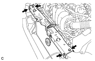
| 5. INSTALL UPPER RADIATOR SUPPORT SUB-ASSEMBLY (for 2AZ-FE) |
Install the upper radiator support sub-assembly with the 4 bolts.
- Torque:
- 5.5 N*m{56 kgf*cm, 49 in.*lbf}
 |
Connect the horn connector.
|
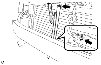
| 6. INSTALL HOOD LOCK SUPPORT SUB-ASSEMBLY (for 2ZR-FE) |
Install the hood lock support sub-assembly with the 2 bolts.
- Torque:
- 7.0 N*m{71 kgf*cm, 62 in.*lbf}
 |
| 7. INSTALL HOOD LOCK SUPPORT SUB-ASSEMBLY (for 2AZ-FE) |
Install the hood lock support sub-assembly with the 2 bolts.
- Torque:
- 7.0 N*m{71 kgf*cm, 62 in.*lbf}
|
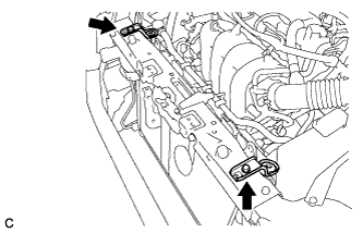
| 8. INSTALL WATER BY-PASS HOSE (for 2ZR-FE) |
Install the water by-pass hose with the 3 clamps.
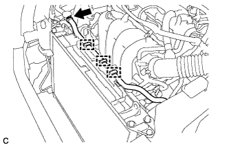 |
Connect the water by-pass hose to the radiator assembly with the clamp.
| 9. INSTALL WATER BY-PASS HOSE (for 2AZ-FE) |
Install the water by-pass hose with the 2 clamps.
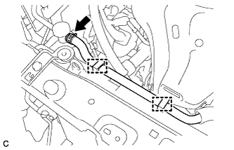 |
Connect the water by-pass hose to the radiator assembly with the clamp.
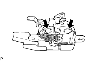
| 10. INSTALL HOOD LOCK ASSEMBLY |
Apply MP grease to the sliding areas of the lock.
 |
Connect the hood lock control cable.
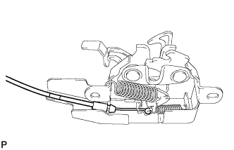 |
Install the hood lock assembly with the 3 bolts.
- Torque:
- Centering Bolt:
- 7.5 N*m{77 kgf*cm, 66 in.*lbf}
- Standard Bolt:
- 8.0 N*m{82 kgf*cm, 71 in.*lbf}
 |
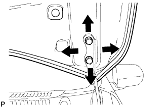
| 11. INSPECT HOOD SUB-ASSEMBLY |
Check that the clearance measurements of areas A through E are within each standard range.

- Standard Clearance:
Area Measurement Area Measurement A 3.1 to 6.1 mm (0.122 to 0.240 in.) D 4.8 mm (0.189 in.) B -1.5 to 1.5 mm (-0.0591 to 0.0591 in.) E 0.7 mm (0.0276 in.) C 2.3 to 5.3 mm (0.0906 to 0.209 in.) - -
| 12. ADJUST HOOD SUB-ASSEMBLY |
Horizontally and vertically adjust the hood.
Loosen the 4 hinge bolts of the hood.
Adjust the clearance between the hood and front fender by moving the hood.
Tighten the 4 hinge bolts after the adjustment.
- Torque:
- 13 N*m{133 kgf*cm, 10 ft.*lbf}
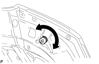
Adjust the height of the front end of the hood using the cushion rubber.
Adjust the cushion rubber so that the heights of the hood and fender are aligned.
- HINT:
- Raise or lower the front end of the hood by turning the cushion rubber.
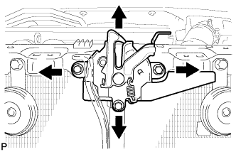
Adjust the hood lock.
Loosen the 3 bolts.
Tighten the bolts after the adjustment.
- Torque:
- 8.0 N*m{82 kgf*cm, 71 in.*lbf}
Check that the striker engages the hood lock smoothly.
| 13. INSTALL UPPER RADIATOR SUPPORT (for 2ZR-FE) |
Install the 2 radiator support cushions to the 2 upper radiator supports.
Install the 2 upper radiator supports with the 2 bolts.
- Torque:
- 19 N*m{194 kgf*cm, 14 ft.*lbf}
 |
| 14. INSTALL UPPER RADIATOR SUPPORT (for 2AZ-FE) |
Install the 2 radiator support cushions to the 2 upper radiator supports.
Install the 2 upper radiator supports with the 2 bolts.
- Torque:
- 19 N*m{194 kgf*cm, 14 ft.*lbf}
 |
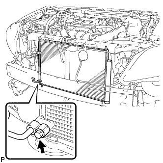
| 15. CONNECT AIR CONDITIONING TUBE ASSEMBLY |
Remove the attached vinyl tape from the tube and the connecting part of the cooler condenser assembly.
Sufficiently apply compressor oil to a new O-ring and the fitting surface of the tube joint.
- Compressor oil:
- ND-OIL 8 or equivalent
Install the O-ring on the air conditioning tube assembly.
Install the air conditioning tube assembly on the cooler condenser assembly with the bolt.
- Torque:
- 5.4 N*m{55 kgf*cm, 48 in.*lbf}
 |
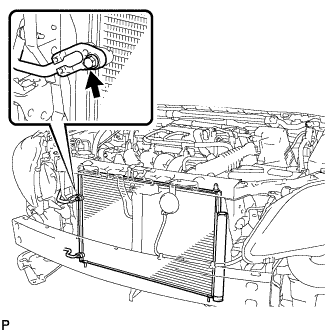
| 16. CONNECT DISCHARGE HOSE SUB-ASSEMBLY |
Remove the attached vinyl tape from the pipe and the connecting part of the cooler condenser assembly.
Sufficiently apply compressor oil to a new O-ring and the fitting surface of the pipe joint.
- Compressor oil:
- ND-OIL 8 or equivalent
Install the O-ring on the discharge hose sub-assembly.
Install the discharge hose sub-assembly on the cooler condenser assembly with the bolt.
- Torque:
- 5.4 N*m{55 kgf*cm, 48 in.*lbf}
 |
| 17. CHARGE WITH REFRIGERANT |
Perform vacuum purging using a vacuum pump.
Charge with refrigerant HFC-134a (R134a).
- Standard:
- 410 to 470 g (14.5 to 16.6 oz.)
- SST
- 09985-20010(09985-02130,09985-02150,09985-02090,09985-02110,09985-02010,09985-02050,09985-02060,09985-02070,09985-02140,09985-02080)
- NOTICE:
- Do not turn the A/C on before charging with refrigerant. Doing so will cause the cooler compressor to work without refrigerant, resulting in overheating of the cooler compressor.
- HINT:
- Ensure that sufficient refrigerant is available to recharge the system when using a refrigerant recovery unit. Refrigerant recovery units are not always able to recover 100% of the refrigerant from an A/C system.
| 18. INSTALL FRONT BUMPER ASSEMBLY (for 2AZ-FE) |
Connect the 2 fog light connectors.
Engage the 6 claws and install the front bumper assembly as shown in the illustration.
 |
Install the 2 screws, 7 clips and 2 bolts.
- Torque:
- Bolt:
- 5.0 N*m{51 kgf*cm, 44 in.*lbf}
Install the pin hold clip.
Text in Illustration *a Correct *b Incorrect - NOTICE:
- Insert the pin hold clip with the slot aligned vertically. Do not rotate the clip after inserting it. After installation, confirm that the slot is vertical.
- HINT:
- Use the same procedure for the RH side and LH side.
 |
| 19. INSTALL FRONT BUMPER ASSEMBLY (for 2ZR-FE) |
w/ Fog Light:
Connect the 2 fog light connectors.
Engage the 6 claws and install the front bumper assembly as shown in the illustration.
|
Install the 4 screws, 7 clips and 2 bolts.
- Torque:
- Bolt:
- 5.0 N*m{51 kgf*cm, 44 in.*lbf}
Install the pin hold clip.
Text in Illustration *a Correct *b Incorrect - NOTICE:
- Insert the pin hold clip with the slot aligned vertically. Do not rotate the clip after inserting it. After installation, confirm that the slot is vertical.
- HINT:
- Use the same procedure for the RH side and LH side.
|
| 20. INSTALL NO. 4 ENGINE UNDER COVER (for 2AZ-FE) |
Install the No. 4 engine under cover with the 4 screws and 4 clips.
| 21. INSTALL RADIATOR GRILLE PROTECTOR |
Install the 2 radiator grille protectors.
- Torque:
- 5.0 N*m{51 kgf*cm, 44 in.*lbf}
| 22. WARM UP ENGINE |
Keep the A/C switch on for at least 2 minutes to warm up the compressor.
- NOTICE:
- Be sure to warm up the compressor when turning the A/C on after removing and installing the cooler refrigerant lines (including the compressor), to prevent damage to the compressor.
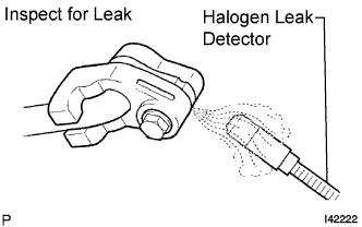
| 23. INSPECT FOR REFRIGERANT LEAK |
After recharging with refrigerant, inspect for refrigerant leaks using a halogen leak detector.
Carry out the test under the following conditions:
- Turn the ignition switch off.
- Secure good ventilation (the halogen leak detector may react to volatile gases which are not refrigerant, such as evaporated gasoline and exhaust gas).
- Repeat the test 2 or 3 times.
- Make sure that there is some refrigerant remaining in the refrigeration system.
When the compressor is off: approx. 392 to 588 kPa (3.9 to 5.9 kgf/cm2, 57 to 85 psi).
- Turn the ignition switch off.
Using a halogen leak detector, inspect for refrigerant leaks from the refrigerant lines.
 |
Bring the halogen leak detector close to the drain hose with the detector's power off, and then turn the detector on.
- HINT:
- After the blower motor has stopped, let the cooling unit stand for more than 15 minutes.
- Bring the halogen leak detector sensor under the drain hose.
- When bringing the halogen leak detector close to the drain hose, make sure that the halogen leak detector does not react to volatile gases.
If it is not possible to avoid interference from volatile gases, the vehicle should be lifted up to allow testing.
 |
If a refrigerant leak is not detected from the drain hose, remove the blower motor control from the cooling unit. Insert the halogen leak detector sensor into the unit and perform the test.
Disconnect the pressure switch connector and leave it for approximately 20 minutes. Bring the halogen leak detector close to the pressure switch and perform the test.
| 24. ADJUST FOG LIGHT AIMING (w/ Fog Light) |