INSTALL AIR CONDITIONING DUCT SUB-ASSEMBLY (for Automatic Air Conditioning System)
INSTALL AIR CONDITIONING HARNESS ASSEMBLY (for Automatic Air Conditioning System)
INSTALL AIR MIX DAMPER CONTROL CABLE SUB-ASSEMBLY (for Manual Air Conditioning System)
INSTALL NO. 2 HEATER CONTROL CABLE SUB-ASSEMBLY (for Manual Air Conditioning System)
INSTALL AIR MIX CONTROL SERVO MOTOR (for TMC Made with Automatic Air Conditioning System)
INSTALL AIR MIX CONTROL SERVO MOTOR (for TMMC Made with Automatic Air Conditioning System)
INSTALL AIR OUTLET CONTROL SERVO MOTOR (for Automatic Air Conditioning System)
Air Conditioning Unit -- Reassembly |
| 1. INSTALL NO. 1 COOLER THERMISTOR |
Install the No. 1 cooler thermistor as shown in the illustration.
Part Length A 34.3 mm 1.35 in. B 20.9 mm 0.823 in. C 50 mm 1.96 in. - NOTICE:
- Be sure to insert the thermistor only once because reinserting it will not allow it to be firmly secured.
- When reusing the evaporator, insert the thermistor one row next to the one that has been used previously (X in the illustration).
- After inserting the thermistor, do not apply excessive force to the wire.
- Directly insert the thermistor until the edge of plastic case "a" comes into contact with evaporator "b".
 |
| 2. INSTALL NO. 1 COOLER EVAPORATOR SUB-ASSEMBLY |
Sufficiently apply compressor oil to 2 new O-rings and the fitting surfaces. Install the 2 O-rings to the No. 1 cooler evaporator sub-assembly.
- Compressor oil:
- ND-OIL 8 or equivalent
- NOTICE:
- Keep the O-rings and O-ring fitting surfaces clean from dirt or foreign matter.
Install the No. 1 cooler evaporator sub-assembly together with the No. 1 cooler thermistor as a set.
 |
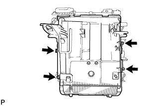
Engage the clamp.
Engage the 4 claws as shown in the illustration.
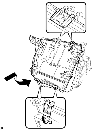 |
Install the lower heater case with the 4 screws.
 |
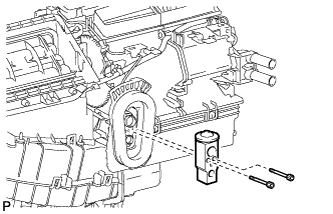
| 3. INSTALL COOLER EXPANSION VALVE |
Using a 4 mm hexagon wrench, install the cooler expansion valve with the 2 hexagon bolts.
- Torque:
- 3.5 N*m{36 kgf*cm, 31 in.*lbf}
 |
| 4. INSTALL HEATER RADIATOR UNIT SUB-ASSEMBLY |
Install the heater radiator unit sub-assembly to the air conditioning unit assembly.
 |
Install the clamp with the screw.
| 5. INSTALL DRAIN COOLER HOSE |
Install the drain cooler hose to the air conditioning unit assembly.
 |
| 6. INSTALL AIR CONDITIONING DUCT SUB-ASSEMBLY (for Automatic Air Conditioning System) |
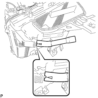
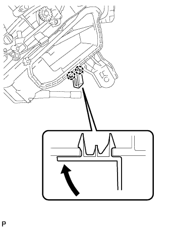
Engage the 2 claws and install the air conditioning duct sub-assembly.
 |
| 7. INSTALL AIR CONDITIONING AMPLIFIER ASSEMBLY |
Engage the claw.
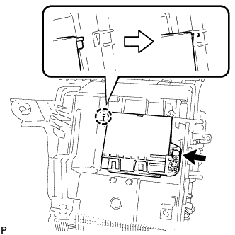 |
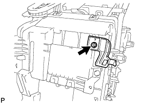
Install the air conditioning amplifier assembly with the screw.
| 8. INSTALL CONSOLE MOUNTING BRACKET LH |
Install the console mounting bracket LH with the screw.
 |
| 9. INSTALL CONSOLE MOUNTING BRACKET RH |
Engage the 2 claws and install the console mounting bracket RH as shown in the illustration.
 |
| 10. INSTALL AIR CONDITIONING HARNESS ASSEMBLY (for Automatic Air Conditioning System) |
Connect the connector.
 |
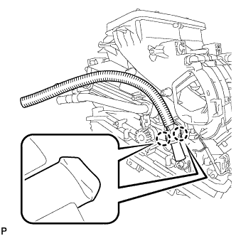
Engage each clamp and install the air conditioning harness assembly.
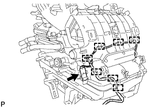
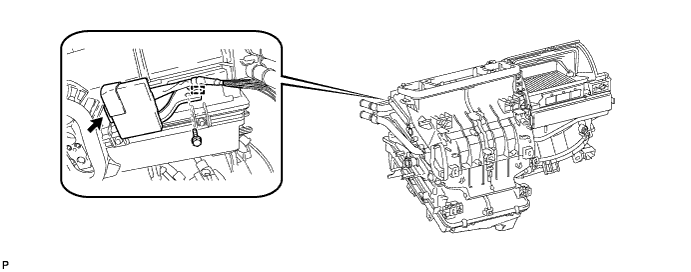
| 11. INSTALL QUICK HEATER ASSEMBLY (w/ PTC Heater) |
Install the quick heater assembly as shown in the illustration.
 |
Install the 2 screws.
 |
Engage each clamp.
| 12. INSTALL AIR MIX DAMPER CONTROL CABLE SUB-ASSEMBLY (for Manual Air Conditioning System) |
Position the gear of the air mix damper control cable sub-assembly and the unit gear as shown in the illustration, and install the air mix damper control cable sub-assembly.
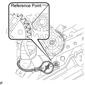 |
| 13. INSTALL NO. 2 HEATER CONTROL CABLE SUB-ASSEMBLY (for Manual Air Conditioning System) |
Position the gear of the No. 2 heater control cable sub-assembly and the unit link as shown in the illustration, and install the No. 2 heater control cable sub-assembly.
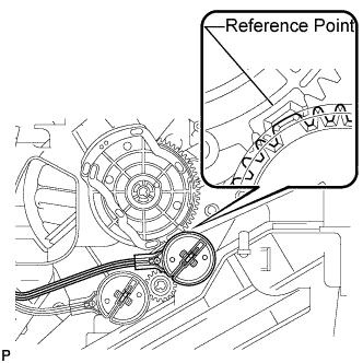 |
| 14. INSTALL AIR MIX CONTROL SERVO MOTOR (for TMC Made with Automatic Air Conditioning System) |
Using the reference point, install the air mix control servo motor with the 3 screws.
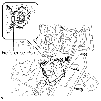 |
Connect the connector.
| 15. INSTALL AIR MIX CONTROL SERVO MOTOR (for TMMC Made with Automatic Air Conditioning System) |
Using the reference point, install the air mix control servo motor with the 2 screws.
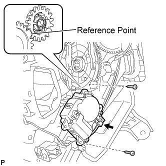 |
Connect the connector.
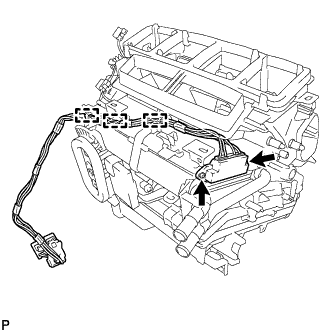
| 16. INSTALL AIR OUTLET CONTROL SERVO MOTOR (for Automatic Air Conditioning System) |
Using the reference point, install the air outlet control servo motor with the 3 screws.
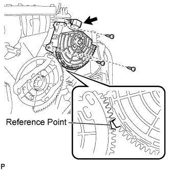 |
Connect the connector.
| 17. INSTALL IMMOBILIZER CODE ECU (w/ Smart Key System) |
Install the immobilizer code ECU with the bolt.
Engage the clamp.
Connect the connector.
| 18. INSTALL TRANSPONDER KEY ECU (w/o Smart Key System) |
Install the transponder key ECU with the bolt.
Engage the clamp.
Connect the connector.