Dtc B1421/21 Solar Sensor Circuit (Passenger Side)
DESCRIPTION
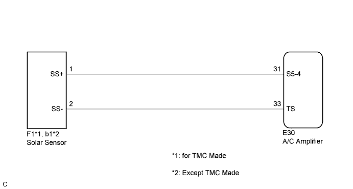
WIRING DIAGRAM
INSPECTION PROCEDURE
READ VALUE USING TECHSTREAM
CHECK HARNESS AND CONNECTOR (SOLAR SENSOR)
CHECK HARNESS AND CONNECTOR (SOLAR SENSOR - A/C AMPLIFIER)
DTC B1421/21 Solar Sensor Circuit (Passenger Side) |
DESCRIPTION
 The solar sensor, which is installed on the upper side of the instrument panel, detects sunlight and controls the air conditioning in AUTO mode. The output voltage from the solar sensor varies according to the amount of sunlight. When the sunlight increases, the output voltage increases. As the sunlight decreases, the output voltage decreases. The A/C amplifier detects voltage output from the solar sensor.
DTC No.
| DTC Detection Condition
| Trouble Area
|
B1421/21
| Open or short in passenger side solar sensor circuit
| - Solar sensor
- Harness or connector between solar sensor and A/C amplifier
- A/C amplifier
|
WIRING DIAGRAM
INSPECTION PROCEDURE
- HINT:
- If the check is performed in a dark place, DTC B1421/21 (solar sensor circuit abnormal) may be output even though the system is normal.
| 1.READ VALUE USING TECHSTREAM |
Connect the Techstream to the DLC3.
Turn the ignition switch to ON.
Turn the Techstream on.
Expose the sensing portion of the solar sensor to light.
- HINT:
- Use an incandescent light for inspection.
Enter the following menus: Body Electrical / Air Conditioner / Data List.
Check the value(s) by referring to the table below.
Air ConditionerTester Display
| Measurement Item/Range
| Normal Condition
| Diagnostic Note
|
Solar Sensor (D side)
(Solar Sens-D)
| Driver side solar sensor / Min.: 0, Max.: 255
| Driver side solar sensor value increases as brightness increases
| -
|
- OK:
- The display is as specified in the "Normal Condition" column.
- Result:
Result
| Proceed to
|
NG
| A
|
OK (When troubleshooting according to Problem Symptoms Table)
| B
|
OK (When troubleshooting according to DTC)
| C
|
| 2.CHECK HARNESS AND CONNECTOR (SOLAR SENSOR) |
Disconnect the connector from the solar sensor.
Measure the voltage according to the value(s) in the table below.
- Standard Voltage:
Tester Connection
| Switch Condition
| Specified Condition
|
F1-1 (SS+) - F1-2 (SS-) *A
| Ignition switch off
| Below 1 V
|
F1-1 (SS+) - F1-2 (SS-) *A
| Ignition switch ON
| 11 to 14 V
|
b1-1 (SS+) - b1-2 (SS-) *B
| Ignition switch off
| Below 1 V
|
b1-1 (SS+) - b1-2 (SS-) *B
| Ignition switch ON
| 11 to 14 V
|
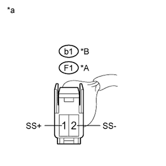
Text in Illustration*A
| for TMC Made
|
*B
| Except TMC Made
|
*a
| Front view of wire harness connector
(to Solar Sensor)
|
| 3.CHECK HARNESS AND CONNECTOR (SOLAR SENSOR - A/C AMPLIFIER) |
Disconnect the connector from the A/C amplifier.
Measure the resistance according to the value(s) in the table below.
- Standard Resistance:
Tester Connection
| Condition
| Specified Condition
|
E30-33 (TS) - F1-2 (SS-) *A
| Always
| Below 1 Ω
|
E30-31 (S5-4) - F1-1 (SS+) *A
| Always
| Below 1 Ω
|
E30-33 (TS) - b1-2 (SS-) *B
| Always
| Below 1 Ω
|
E30-31 (S5-4) - b1-1 (SS+) *B
| Always
| Below 1 Ω
|
E30-33 (TS) - Body ground
| Always
| 10 kΩ or higher
|
E30-31 (S5-4) - Body ground
| Always
| 10 kΩ or higher
|
Text in Illustration*A
| for TMC Made
|
*B
| Except TMC Made
|
| | REPAIR OR REPLACE HARNESS OR CONNECTOR |
|
|