Vehicle Interior. Corolla. Zre142 Aze141
Heating Air Conditioning. Corolla. Zre142 Aze141
Air Conditioning System (For Automatic Air Conditioning System) -- Terminals Of Ecu |
| A/C AMPLIFIER |
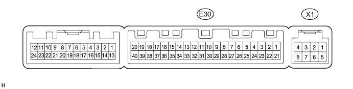
- HINT:
- Check from the rear of the connector while it is connected to the A/C amplifier.
| Terminal No. (Symbol) | Wiring Color | Terminal Description | Condition | Specified Condition |
| E30-1 (IG+) - E30-14 (GND) | Y - W-B*1 R - W-B*2 | Power source (IG) | Ignition switch: ON | 11 to 14 V |
| E30-1 (IG+) - E30-14 (GND) | Y - W-B*1 R - W-B*2 | Power source (IG) | Ignition switch: off | Below 1 V |
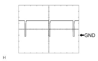
| E30-2 (SOL+) - E30-14 (GND) | LG - W-B*1 V - W-B*2 | Compressor assembly with pulley operation signal | Engine running A/C switch: ON Blower switch: LO | Pulse generation (See waveform 1) |
| E30-3 (PTC1) - E30-14 (GND)*3 | W - W-B*1 P - W-B*2 | PTC heater operation signal | Engine running (1250 rpm or higher) Temperature setting: MAX. HOT Ambient temperature: 10°C (50°F) or lower Engine coolant temperature: 75°C (167°F) or lower Light control switch: OFF Blower switch: ON | 11 to 14 V |
| E30-7 (FLOQ) - E30-35 (SG-4)*4 | R - W | A/C flow sensor signal | Ignition switch: ON A/C switch: OFF | 3.8 to 4.2 V |
| E30-7 (FLOQ) - E30-35 (SG-4)*4 | R - W | A/C flow sensor signal | Ignition switch: ON A/C switch: ON Blower switch: HI | 0.7 to 3.8 V |
| E30-9 (PRE) - E30-13 (SG-2) | L - G | A/C pressure sensor signal | Engine running, A/C system operating, Refrigerant pressure: Abnormal pressure (more than 3140 kPa (32.0 kgf/cm2, 455 psi)) | 4.848 V or higher |
| E30-9 (PRE) - E30-13 (SG-2) | L - G | A/C pressure sensor signal | Engine running, A/C system operating, Refrigerant pressure: Abnormal pressure (less than 196 kPa (2.0 kgf/cm2, 28 psi)) | Below 0.734 V |
| E30-9 (PRE) - E30-13 (SG-2) | L - G | A/C pressure sensor signal | Engine running, A/C system operating, Refrigerant pressure: Normal pressure (less than 3140 kPa (32.0 kgf/cm2, 455 psi) and more than 196 kPa (2.0 kgf/cm2, 28 psi)) | 0.734 to 4.848 V |
| E30-10 (S5-3) - E30-13 (SG-2) | B - G | Power supply for A/C pressure sensor | Ignition switch: ON | 4.75 to 5.25 V |
| E30-10 (S5-3) - E30-13 (SG-2) | B - G | Power supply for A/C pressure sensor | Ignition switch: off | Below 1 V |
| E30-11 (CANH) - E30-12 (CANL) | V - W | CAN communication circuit | Ignition switch: ON | Pulse generation |
| E30-13 (SG-2) - Body ground | G - Body ground | Ground for A/C pressure sensor | Always | Below 1 V |
| E30-14 (GND) - Body ground | W-B - Body ground | Ground for main power supply | Always | Below 1 V |
| E30-21 (B) - E30-14 (GND) | W - W-B*1 BR - W-B*2 | Power source (Back-up) | Always | 11 to 14 V |
| E30-22 (PTC2) - E30-14 (GND)*3 | B - W-B | PTC heater operation signal | Engine running (1250 rpm or higher) Temperature setting: MAX. HOT Ambient temperature: 10°C (50°F) or lower Engine coolant temperature: 70°C (158°F) or lower Light control switch: OFF Blower switch: ON | 11 to 14 V |
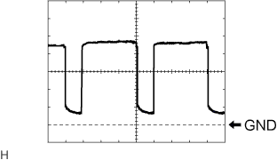
| E30-23 (BLW) - E30-14 (GND) | R - W-B*1 L - W-B*2 | Blower motor speed control signal | Ignition switch: ON Blower switch: ON | Pulse generation (See waveform 2) |
| E30-25 (ALT) - E30-14 (GND)*3 | L - W-B | Alternator signal (PTC Heater line control) | Engine started | Pulse generation |
| E30-27 (HLS) - E30-14 (GND)*3 | B - W-B*1 V - W-B*2 | Headlight signal (PTC Heater line control) | Engine started Headlight switch: OFF | 11 to 14 V |
| E30-27 (HLS) - E30-14 (GND)*3 | B - W-B*1 V - W-B*2 | Headlight signal (PTC Heater line control) | Engine started Headlight switch: ON | Below 1 V |
| E30-29 (TR) - E30-34 (SG-1) | GR - V*1, W - SB*2 | Room temperature sensor signal | Ignition switch: ON Cabin temperature at 25°C (77°F) | 1.8 to 2.2 V |
| E30-29 (TR) - E30-34 (SG-1) | GR - V*1, W - SB*2 | Room temperature sensor signal | Ignition switch: ON Cabin temperature at 40°C (104°F) | 1.2 to 1.6 V |
| E30-30 (S5-1) - E30-35 (SG-4)*4 | B - W | Power supply for A/C flow sensor | Ignition switch: ON | 4.5 to 5.5 V |
| E30-30 (S5-1) - E30-35 (SG-4)*4 | B - W | Power supply for A/C flow sensor | Ignition switch: off | Below 1 V |
| E30-31 (S5-4) - E30-14 (GND) | LG - W-B*1 Y - W-B*2 | Solar sensor power source | Ignition switch: ON | 4.5 to 5.5 V |
| E30-31 (S5-4) - E30-14 (GND) | LG - W-B*1 Y - W-B*2 | Solar sensor power source | Ignition switch: off | Below 1 V |
| E30-33 (TS) - E30-14 (GND) | P - W-B*1 R - W-B*2 | Solar sensor signal | Ignition switch: ON Solar sensor subjected to light. | 0.8 to 4.3 V |
| E30-33 (TS) - E30-14 (GND) | P - W-B*1 R - W-B*2 | Solar sensor signal | Ignition switch: ON Solar sensor covered with cloth. | Below 0.8 V |
| E30-34 (SG-1) - Body ground | V - Body ground*1 SB - Body ground*2 | Ground for room temperature sensor | Always | Below 1 V |
| E30-35 (SG-4) - Body ground*4 | W - Body ground | Ground for A/C flow sensor | Always | Below 1 V |
| E30-37 (LIN1) - E30-14 (GND) | SB - W-B*1 LG - W-B*2 | LIN communication signal | Ignition switch: ON | Pulse generation |
| E30-38 (RDFG) - E30-14 (GND) | B - W-B*1 BE - W-B*2 | DEF relay signal | Ignition switch: ON REAR DEF switch: ON | Below 1 V |
| E30-38 (RDFG) - E30-14 (GND) | B - W-B*1 BE - W-B*2 | DEF relay signal | Ignition switch: ON REAR DEF switch: OFF | 11 to 14 V |
| X1-2 (BUS G) - Body ground | - | Ground for BUS IC | Always | Below 1 V |
| X1-3 (BUS) - X1-2 (BUS G) | - | BUS IC control signal | Ignition switch off → ON | Pulse generation |
| X1-4 (B BUS) - X1-2 (BUS G) | - | Power supply for BUS IC | Always | 11 to 14 V |
| X1-5 (SGA) - Body ground | - | Ground for evaporator temperature sensor | Always | Below 1 V |
| X1-6 (TEA) - X1-5 (SGA) | - | Evaporator temperature sensor signal | Ignition switch: ON Evaporator temperature at 0°C (32°F) | 1.7 to 2.1 V |
| X1-6 (TEA) - X1-5 (SGA) | - | Evaporator temperature sensor signal | Ignition switch: ON Evaporator temperature at 15°C (59°F) | 0.9 to 1.3 V |
- *1: for TMC Made
- *2: except TMC Made
- *3: w/ PTC Heater Assembly
- *4: for 2ZR-FE
Waveform 1
Item Content Terminal No. (Symbol) E30-2 (SOL+) - E30-14 (GND) Tool Setting 5 V/DIV., 500 μs./DIV. Vehicle Condition Engine is running
A/C switch: ON
Blower Switch: LOWaveform 2
Item Content Terminal No. (Symbol) E30-23 (BLW) - E30-14 (GND) Tool Setting 1 V/DIV., 500 μs./DIV. Vehicle Condition Ignition switch ON
Blower switch: ON
 |
 |
| A/C CONTROL ASSEMBLY |

- HINT:
- Check from the rear of the connector while it is connected to the A/C control assembly.
| Terminal No. (Symbol) | Wiring Color | Terminal Description | Condition | Specified Condition |
| E16-2 (GND) - Body ground | W-B - Body ground | Ground for A/C control assembly | Always | Below 1 V |
| E16-3 (LIN1) - E16-2 (GND) | SB - W-B*1 LG - W-B*2 | LIN communication circuit | Ignition switch: ON | Pulse generation |
| E16-5 (IG+) - E16-2 (GND) | B - W-B*1 V - W-B*2 | Power source (IG) | Ignition switch: off | Below 1 V |
| E16-5 (IG+) - E16-2 (GND) | B - W-B*1 V - W-B*2 | Power source (IG) | Ignition switch: ON | 11 to 14 V |
- *1: for TMC Made
- *2: except TMC Made