Engine Immobiliser System (W/O Smart Key System) Security Indicator Light Circuit
DESCRIPTION
WIRING DIAGRAM
INSPECTION PROCEDURE
PERFORM ACTIVE TEST USING TECHSTREAM
CHECK HARNESS AND CONNECTOR (TRANSPONDER KEY ECU - SECURITY INDICATOR LIGHT)
CHECK HARNESS AND CONNECTOR (SECURITY INDICATOR LIGHT - BODY GROUND)
ENGINE IMMOBILISER SYSTEM (w/o Smart Key System) - Security Indicator Light Circuit |
DESCRIPTION
The security indicator light blinks continuously due to a continuous signal received from the transponder key ECU assembly while in the armed state.
WIRING DIAGRAM
INSPECTION PROCEDURE
- NOTICE:
- If the transponder key ECU assembly is replaced, register the key and ECU communication ID (COROLLA_ZRE142 RM00000120Y02CX.html).
| 1.PERFORM ACTIVE TEST USING TECHSTREAM |
Connect the Techstream to the DLC3.
Turn the ignition switch to ON.
Turn the Techstream on.
Enter the following menus: Body Electrical / Immobiliser / Active Test.
Perform the Active Test according to the display on the Techstream.
Immobiliser (Transponder Key ECU Assembly)Tester Display
| Test Part
| Control Range
| Diagnostic Note
|
Security Indicator
| Security indicator light
| ON/OFF
| -
|
- OK:
- The security indicator turns on and off according to the Techstream operation.
| 2.CHECK HARNESS AND CONNECTOR (TRANSPONDER KEY ECU - SECURITY INDICATOR LIGHT) |
Disconnect the transponder key ECU assembly connector.
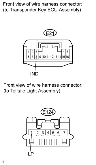
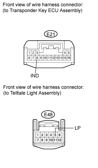
Disconnect the telltale light assembly connector.
for Telltale Light (w/o Clock):
Measure the resistance according to the value(s) in the table below.
- Standard Resistance:
Tester Connection
| Condition
| Specified Condition
|
E21-8 (IND) - E124-1 (LP)
| Always
| Below 1 Ω
|
E21-8 (IND) - Body ground
| Always
| 10 kΩ or higher
|
for Telltale Light (w/ Clock):
Measure the resistance according to the value(s) in the table below.
- Standard Resistance:
Tester Connection
| Condition
| Specified Condition
|
E21-8 (IND) - E48-5 (LP)
| Always
| Below 1 Ω
|
E21-8 (IND) - Body ground
| Always
| 10 kΩ or higher
|
| | REPAIR OR REPLACE HARNESS OR CONNECTOR |
|
|
| 3.CHECK HARNESS AND CONNECTOR (SECURITY INDICATOR LIGHT - BODY GROUND) |
for Telltale Light (w/o Clock):
Measure the resistance according to the value(s) in the table below.
- Standard Resistance:
Tester Connection
| Condition
| Specified Condition
|
E124-2 (E) - Body ground
| Always
| Below 1 Ω
|
for Telltale Light (w/ Clock):
Measure the resistance according to the value(s) in the table below.
- Standard Resistance:
Tester Connection
| Condition
| Specified Condition
|
E48-12 (E) - Body ground
| Always
| Below 1 Ω
|
| | REPAIR OR REPLACE HARNESS OR CONNECTOR |
|
|