INSTALL IGNITION OR STARTER SWITCH ASSEMBLY (for Manual Transaxle)
INSTALL IGNITION OR STARTER SWITCH ASSEMBLY (for Automatic Transaxle)
INSTALL TURN SIGNAL SWITCH ASSEMBLY WITH SPIRAL CABLE SUB-ASSEMBLY
Unlock Warning Switch -- Installation |
| 1. INSTALL UNLOCK WARNING SWITCH ASSEMBLY |
Make sure that the ignition switch lock cylinder assembly is in the ACC position.
 |
Install the ignition switch lock cylinder assembly to the steering lock sub-assembly.
Make sure that the ignition switch lock cylinder assembly is securely installed.
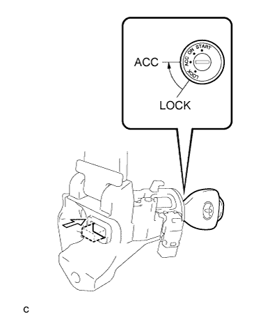
| 2. INSTALL IGNITION SWITCH LOCK CYLINDER ASSEMBLY |
Make sure that the ignition switch lock cylinder assembly is in the ACC position.
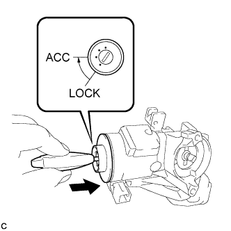 |
Install the ignition switch lock cylinder assembly to the steering lock sub-assembly.
Make sure that the ignition switch lock cylinder assembly is securely installed.
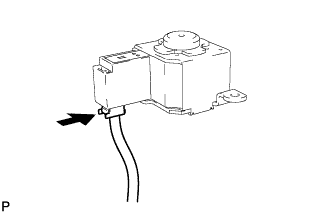
| 3. INSTALL SOLENOID WIRE (for Automatic Transaxle) |
Install the solenoid wire to the steering column upper bracket.
 |
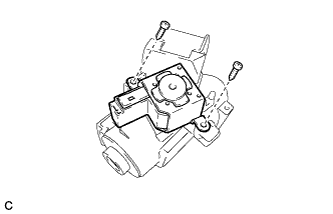
| 4. INSTALL KEY INTERLOCK SOLENOID |
Connect the solenoid wire connector to the key interlock solenoid.
 |
Install the key interlock solenoid to the steering column upper bracket with the 2 screws.
 |
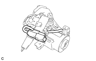
| 5. INSTALL IGNITION OR STARTER SWITCH ASSEMBLY (for Manual Transaxle) |
Install the ignition or starter switch assembly to the steering column upper bracket with the 2 screws.
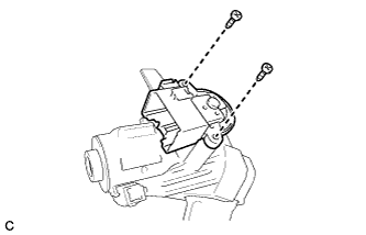 |
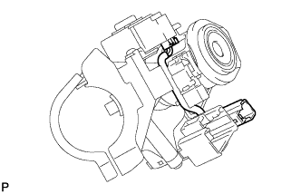
| 6. INSTALL IGNITION OR STARTER SWITCH ASSEMBLY (for Automatic Transaxle) |
Install the ignition or starter switch assembly to the steering column upper bracket with the 2 screws.
|
Install the solenoid wire connector to the ignition or starter switch assembly.
 |
Make sure that the solenoid wire runs securely through the gap of the steering column upper bracket as shown in the illustration.
 |
| 7. INSPECT STEERING LOCK OPERATION |
Check that the steering lock mechanism is activated when the key is removed.
 |
Check that the steering lock mechanism is deactivated when the key is inserted and turned to the ACC position.
- HINT:
- If there is any abnormality, replace the ignition switch lock cylinder assembly or steering column upper with switch bracket assembly.
 |
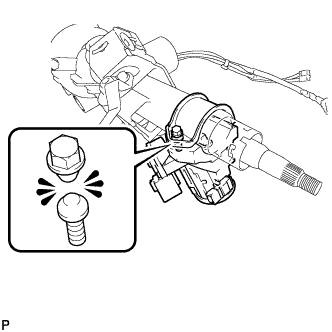
| 8. INSTALL STEERING COLUMN UPPER WITH SWITCH BRACKET ASSEMBLY |
Secure the steering column assembly in a vise.
Temporarily install the steering column upper with switch bracket assembly to the steering column assembly with a new tapered-head bolt.
- NOTICE:
- Be sure to use a new tapered-head bolt.
Tighten the tapered-head bolt until the bolt heads break off.
 |
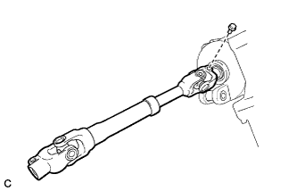
| 9. INSTALL NO. 2 STEERING INTERMEDIATE SHAFT ASSEMBLY |
Align the matchmarks on the No. 2 steering intermediate shaft assembly and the steering column assembly.
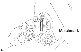 |
Install the bolt.
- Torque:
- 35 N*m{360 kgf*cm, 26 ft.*lbf}
 |
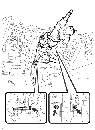
| 10. INSTALL STEERING POST ASSEMBLY (for 2ZR-FE) |
Check that the 2 bushings are securely installed to the steering column assembly.
- HINT:
- If the bushings are missing or damaged, replace the steering column assembly with a new one.
 |
Install the steering post assembly with the bolt and 2 nuts.
- Torque:
- Bolt:
- 36 N*m{367 kgf*cm, 27 ft.*lbf}
- Nut:
- 25 N*m{255 kgf*cm, 18 ft.*lbf}
- NOTICE:
- Do not damage the 2 bushings.
- Do not line up the bolt hole by prying on the collar or bushings. Only install the bolt in straight, without applying any force to the bushings.
- There are two different bolt sizes (12 mm (0.472 in.) or 14 mm (0.551 in.)) available.
 |
Connect the connectors and engage the wire harness clamps to the steering column assembly.
Connect the 2 connectors to the power steering ECU assembly.
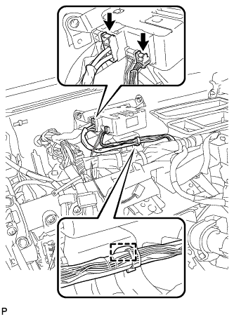 |
Install the wire harness clamp to the power steering ECU assembly.
| 11. INSTALL STEERING POST ASSEMBLY (for 2AZ-FE) |
Check that the 2 bushings are securely installed to the steering column assembly.
- HINT:
- If the bushings are missing or damaged, replace the steering column assembly with a new one.
|
Install the steering post assembly with the bolt and 2 nuts.
- Torque:
- Bolt:
- 36 N*m{367 kgf*cm, 27 ft.*lbf}
- Nut:
- 25 N*m{255 kgf*cm, 18 ft.*lbf}
- NOTICE:
- Do not damage the 2 bushings.
- Do not line up the bolt hole by prying on the collar or bushings. Only install the bolt in straight, without applying any force to the bushings.
- There are two different bolt sizes (12 mm (0.472 in.) or 14 mm (0.551 in.)) available.
|
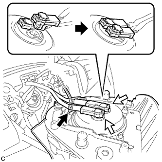
Connect the connectors and engage the wire harness clamps to the steering column assembly.
Engage the wire harness clamp to the power steering ECU assembly.
 |
Connect the connector to the power steering ECU assembly.
 |
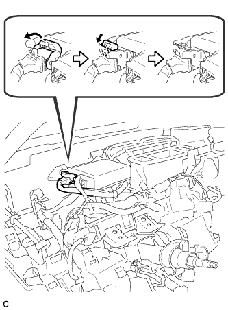
Connect the connector to the power steering ECU assembly.
- HINT:
- Return the lock lever to the original position, engage the claw, and push in the lock of the lock lever, as shown in the illustration.
 |
| 12. TURN FRONT WHEELS TO FACE STRAIGHT AHEAD |
| 13. CONNECT NO. 2 STEERING INTERMEDIATE SHAFT ASSEMBLY |
Align the matchmarks on the No. 2 steering intermediate shaft assembly and the steering intermediate shaft assembly.
 |
Install the bolt.
- Torque:
- 35 N*m{360 kgf*cm, 26 ft.*lbf}
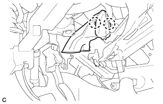
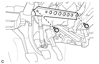
| 14. INSTALL STOP LIGHT SWITCH ASSEMBLY |
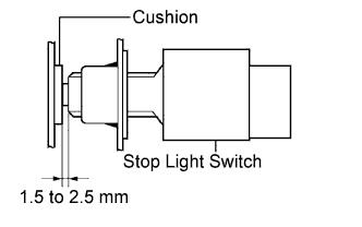
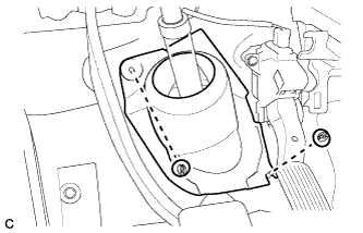
Insert the stop light switch assembly until the rod hits the cushion.
- NOTICE:
- When inserting the stop light switch assembly, support the pedal from behind so that the pedal is not pushed in.
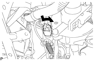 |
Make a quarter turn clockwise to install the stop light switch assembly.
- Torque:
- 1.5 N*m{15 kgf*cm, 13 in.*lbf}or less
- NOTICE:
- When inserting the stop light switch assembly, support the pedal from behind so that the pedal is not pushed in.
 |
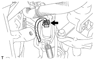
Connect the connector.
 |
Check the protrusion of the rod.
- Protrusion of the rod:
- 1.5 to 2.5 mm (0.059 to 0.098 in.)
- NOTICE:
- Do not depress the brake pedal.
 |
| 15. INSTALL NO. 3 AIR DUCT SUB-ASSEMBLY |
Engage the 2 claws and install the No. 3 air duct sub-assembly.
 |
| 16. INSTALL INSTRUMENT PANEL SUB REINFORCEMENT |
Install the instrument panel sub reinforcement with the 2 bolts.
 |
| 17. INSTALL COLUMN HOLE COVER SILENCER SHEET |
Install the column hole cover silencer sheet with the 2 clips.
 |
Install the floor carpet.
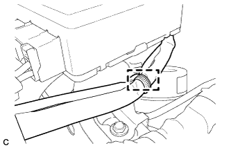
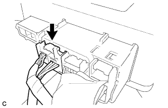
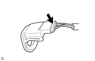
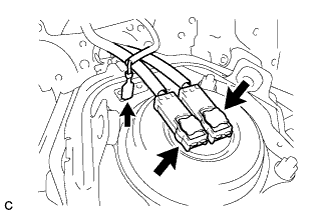
| 18. INSTALL TRANSPONDER KEY AMPLIFIER |
Connect the connector to the transponder key amplifier.
 |
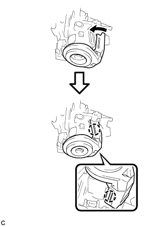
Align the transponder key amplifier with the steering column upper bracket. Tilt the amplifier slightly and slide it into position.
Push the transponder key amplifier, and engage the 2 claws to install the transponder key amplifier to the steering column upper bracket.
 |
| 19. INSTALL UPPER INSTRUMENT PANEL SUB-ASSEMBLY |
- HINT:
- Refer to the instructions for Installation of the upper instrument panel (Link).
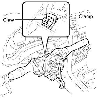
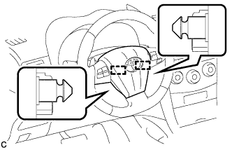
| 20. INSTALL TURN SIGNAL SWITCH ASSEMBLY WITH SPIRAL CABLE SUB-ASSEMBLY |
Using pliers, engage the claw. Install the turn signal switch assembly with spiral cable sub-assembly to the steering column assembly.
 |
Install the connectors to the turn signal switch assembly with spiral cable sub-assembly.
| 21. INSTALL UPPER STEERING COLUMN COVER |
Engage the claw and the 2 pins, and install the upper steering column cover.
 |
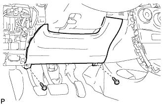
| 22. INSTALL LOWER STEERING COLUMN COVER |
- NOTICE:
- If the lower steering column cover is installed in the incorrect order, it will not be possible to assemble the lower steering column cover.
Engage the 2 claws to install the lower steering column cover.
 |
Engage the 4 claws.
 |
Engage the claw.
- HINT:
- Press the area around the claw to engage it.
 |
| 23. INSTALL LOWER INSTRUMENT PANEL FINISH PANEL SUB-ASSEMBLY |
Engage the 5 claws, 2 clips and 2 guides.
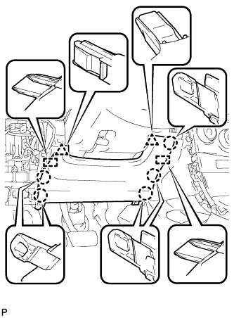 |
Install the lower instrument panel finish panel sub-assembly with the 2 screws <B>.
 |
| 24. TURN FRONT WHEELS TO FACE STRAIGHT AHEAD |
| 25. ADJUST SPIRAL CABLE |
Check that the ignition switch is off.
Check that the cable is disconnected from the negative (-) battery terminal.
- CAUTION:
- Wait at least 90 seconds after disconnecting the cable from the negative (-) battery terminal to disable the SRS system.
Rotate the spiral cable counterclockwise slowly by hand until it stops.
- NOTICE:
- Do not turn the spiral cable using the airbag wire harness.
 |
Rotate the spiral cable clockwise approximately 2.5 turns to align the marks.
- NOTICE:
- Do not turn the spiral cable using the airbag wire harness.
- HINT:
- The spiral cable will rotate approximately 2.5 turns to both the left and right from the center.
 |
| 26. INSTALL STEERING WHEEL ASSEMBLY |
for Type A:
Align the matchmarks on the steering wheel assembly and steering main shaft.
Text in Illustration *a Matchmark Install the steering wheel assembly set nut.
- Torque:
- 50 N*m{510 kgf*cm, 37 ft.*lbf}
Connect the connectors to the spiral cable sub-assembly.

for Type B:
Align the matchmarks on the steering wheel assembly and steering main shaft.
Text in Illustration *a Matchmark Install the steering wheel assembly set nut.
- Torque:
- 50 N*m{510 kgf*cm, 37 ft.*lbf}
Connect the connectors to the spiral cable sub-assembly.

| 27. INSTALL STEERING PAD |
for Type A:
Check that the ignition switch is off.
Check that the cable is disconnected from the negative (-) battery terminal.
- CAUTION:
- Wait at least 90 seconds after disconnecting the cable from the negative (-) battery terminal to disable the SRS system.
Connect the 2 airbag connectors to the steering pad.
- NOTICE:
- When connecting any airbag connector, take care not to damage the airbag wire harness.
Push in the 2 locks to install the airbag connectors.
Connect the horn connector to the steering pad.
Confirm that the circumference groove of the "TORX" screw fits in the screw case, and place the steering pad onto the steering wheel assembly.
Using a "TORX" socket wrench (T30), tighten the 2 "TORX" screws.

Text in Illustration *A w/o Steering Pad Switch *B w/ Steering Pad Switch *1 "Torx" Screw *2 Screw Case - Torque:
- 8.8 N*m{90 kgf*cm, 78 in.*lbf}
for Type B:
Check that the ignition switch is off.
Check that the cable is disconnected from the negative (-) battery terminal.
- CAUTION:
- Wait at least 90 seconds after disconnecting the cable from the negative (-) battery terminal to disable the SRS system.
Connect the 2 airbag connectors to the steering pad.
- NOTICE:
- When connecting any airbag connector, take care not to damage the airbag wire harness.
Push in the 2 locks to install the airbag connectors.
Connect the horn connector to the steering pad.
Push the steering pad to engage the 2 pins.
- NOTICE:
- Make sure that the pins are securely inserted into the steering wheel holes.
| 28. INSTALL LOWER NO. 3 STEERING WHEEL COVER |
for Type A:
Engage the claw to install the lower No. 3 steering wheel cover.
for Type B:
Engage the 2 claws to install the lower No. 3 steering wheel cover.
| 29. INSTALL LOWER NO. 2 STEERING WHEEL COVER |
for Type A:
Engage the claw to install the lower No. 2 steering wheel cover.
for Type B:
Engage the 2 claws to install the lower No. 2 steering wheel cover.
| 30. INSPECT STEERING WHEEL CENTER POINT |
| 31. CONNECT CABLE TO NEGATIVE BATTERY TERMINAL |
| 32. INSPECT STEERING PAD |
Make sure that the horn sounds.
- HINT:
- If the horn does not sound, inspect the horn system (COROLLA_ZRE142 RM0000016F5071X.html).
| 33. INSPECT SRS WARNING LIGHT |