Vehicle Interior. Corolla. Zre142 Aze141
Door Lock. Corolla. Zre142 Aze141
Wireless Door Lock Control System (W/O Smart Key System) -- Terminals Of Ecu |
| CHECK MAIN BODY ECU (INSTRUMENT PANEL JUNCTION BLOCK) |
Disconnect the 2A, 2B, 2C, 2E, 2F and 2G junction block connectors and E61 main body ECU connector.
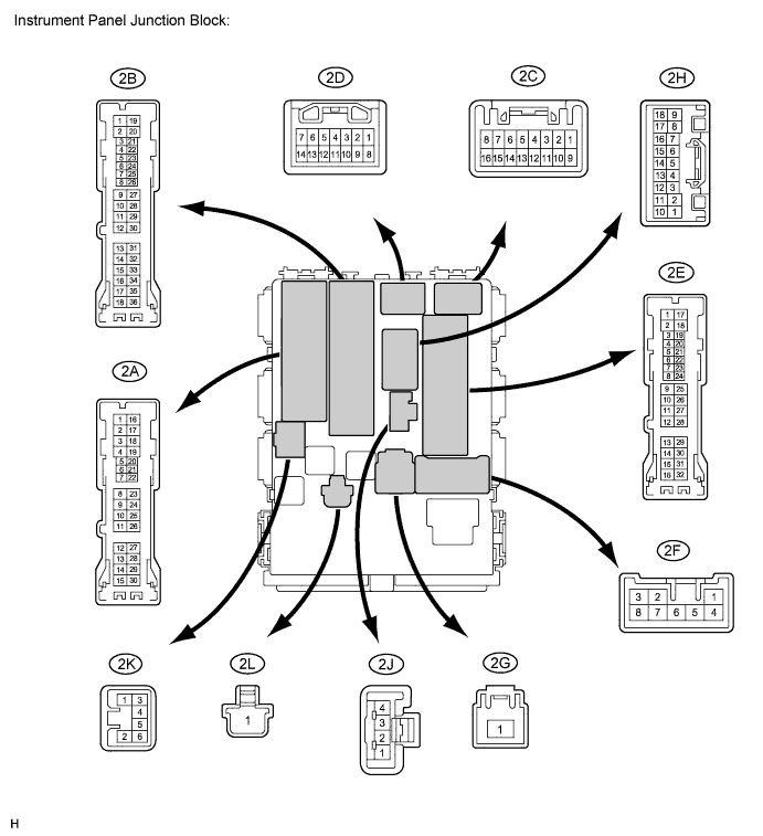
Measure the resistance and voltage between each terminal of the wire harness side connectors and body ground.
If the result is not as specified, there may be a malfunction on the wire harness side.Tester Connection Wiring Color Terminal Description Condition Specified Condition 2A-7 (LGCY) - Body ground LG - Body ground Luggage compartment door courtesy light switch input Luggage compartment door CLOSED (OFF) → OPEN (ON) 10 kΩ or higher → Below 1 Ω 2E-20 (PCTY) - Body ground BR - Body ground*1
BE - Body ground*2Passenger side door courtesy light switch input Passenger side door CLOSED (OFF) → OPEN (ON) 10 kΩ or higher → Below 1 Ω 2B-30 (BECU) - Body ground W - Body ground +B power supply Always 11 to 14 V 2A-21 (DCTY) - Body ground W - Body ground*1
V - Body ground*2Driver side door courtesy light switch input Driver side door CLOSED (OFF) → OPEN (ON) 10 kΩ or higher → Below 1 Ω 2E-17 (GND1) - Body ground W-B - Body ground Ground Always Below 1 Ω 2E-19 (RCTY) - Body ground LG - Body ground*1
Y - Body ground*2Rear courtesy light switch RH input Rear door RH CLOSED (OFF) → OPEN (ON) 10 kΩ or higher → Below 1 Ω 2E-23 (KSW) - Body ground L - Body ground Unlock warning switch input No key in ignition key cylinder (OFF) → Key inserted (ON) 10 kΩ or higher → Below 1 Ω 2F-5 (ACC) - Body ground W - Body ground*1
L - Body ground*2Ignition power supply (ACC signal) Ignition switch ACC → off 11 to 14 V → Below 1 V 2G-1 (IG) - Body ground W - Body ground Ignition power supply (IG signal) Ignition switch ON → off 11 to 14 V → Below 1 V 2G-1 (ALTB) - Body ground W - Body ground +B (power system alternator system) power supply Always 11 to 14 V E61-13 (LCTY) - Body ground SB - Body ground*1
B - Body ground*2Rear courtesy light switch LH input Rear door LH CLOSED (OFF) → OPEN (ON) 10 kΩ or higher → Below 1 Ω - *1: for TMC Made
- *2: Except for TMC made
- *1: for TMC Made
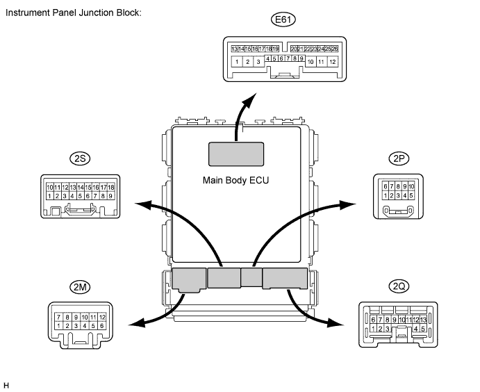
Reconnect the main body ECU and instrument panel junction block connectors.
Measure the voltage between each terminal of the wire harness side connectors and body ground.
Tester Connection Wiring Color Terminal Description Condition Specified Condition 2S-17 (HAZ) - Body ground GR - Body ground Turn signal flasher relay signal Transmitter LOCK or UNLOCK switch is pressed → not pressed Below 1 V* → 11 to 14 V - *: When operating the answer back function.
- *: When operating the answer back function.