DESCRIPTION
WIRING DIAGRAM
INSPECTION PROCEDURE
INSPECT FUSE (DOOR)
CHECK DOOR LOCK OPERATION (ALL DOORS LOCK / UNLOCK)
CHECK DOOR LOCK OPERATION (DOOR CONTROL SWITCH)
READ VALUE USING TECHSTREAM (DOOR CONTROL SWITCH (DRIVER SIDE))
INSPECT DOOR CONTROL SWITCH ASSEMBLY (DRIVER SIDE)
CHECK HARNESS AND CONNECTOR (JUNCTION BLOCK - DOOR CONTROL SWITCH (DRIVER SIDE))
READ VALUE USING TECHSTREAM (DOOR CONTROL SWITCH (PASSENGER SIDE))
INSPECT DOOR CONTROL SWITCH ASSEMBLY (PASSENGER SIDE)
CHECK HARNESS AND CONNECTOR (JUNCTION BLOCK - DOOR CONTROL SWITCH (PASSENGER SIDE))
CHECK DOOR LOCK OPERATION (DOOR KEY CYLINDER)
READ VALUE USING TECHSTREAM (DOOR KEY LINKED LOCK AND UNLOCK SWITCH (DRIVER SIDE))
INSPECT FRONT DOOR LOCK ASSEMBLY (DRIVER SIDE)
CHECK HARNESS AND CONNECTOR (FRONT DOOR LOCK - MAIN BODY ECU (INSTRUMENT PANEL J/B))
READ VALUE USING TECHSTREAM (DOOR KEY LINKED LOCK AND UNLOCK SWITCH (PASSENGER SIDE))
INSPECT FRONT DOOR LOCK ASSEMBLY (PASSENGER SIDE)
CHECK HARNESS AND CONNECTOR (FRONT DOOR LOCK - INSTRUMENT PANEL JUNCTION BLOCK)
POWER DOOR LOCK CONTROL SYSTEM - All Doors LOCK / UNLOCK Functions do not Operate Via Master Switch, Both Front Door Key Cylinders |
DESCRIPTION
The main body ECU (instrument panel junction block) receives switch signals from the door control switch and front door key cylinder, and activates the door lock motor on each door according to these signals.
WIRING DIAGRAM
INSPECTION PROCEDURE
Remove the DOOR fuse from the instrument panel junction block.
Measure the resistance according to the value(s) in the table below.
- Standard Resistance:
Tester Connection
| Condition
| Specified Condition
|
DOOR fuse
| Always
| Below 1 Ω
|
| 2.CHECK DOOR LOCK OPERATION (ALL DOORS LOCK / UNLOCK) |
All doors can be locked/unlocked at once using the following:
- Door control switch on the driver side (switch operation)
- Door control switch on the passenger side (switch operation)
- Door key cylinder linked with door lock on the driver side (key operation)
- Door key cylinder linked with door lock on the passenger side (key operation) (w/o Wireless Door Control System)
Proceed to the next step according to symptom if all the doors cannot be locked/unlocked at once.
- Result:
Result
| Proceed to
|
All doors cannot be locked/unlocked at once by using door control switch.
| A
|
All doors cannot be locked/unlocked at once by using door key cylinder.
| B
|
| 3.CHECK DOOR LOCK OPERATION (DOOR CONTROL SWITCH) |
Proceed to the next step according to symptom if all the doors cannot be locked/unlocked at once.
- Result:
Result
| Proceed to
|
All doors cannot be locked/unlocked at once by using door control switch on driver side or power window master switch.
| A
|
All doors cannot be locked/unlocked at once by using door control switch on passenger side.
| B
|
All doors cannot be locked/unlocked at once by using both driver and passenger side door control switch.
| C
|
| |
|
| | REPLACE MAIN BODY ECU (INSTRUMENT PANEL JUNCTION BLOCK) |
|
|
| 4.READ VALUE USING TECHSTREAM (DOOR CONTROL SWITCH (DRIVER SIDE)) |
Connect the Techstream
Turn the ignition switch to ON.
Turn the Techstream on.
Enter the following menus: Body Electrical / Main Body / Data List.
Read the Data List according to the display on the Techstream.
Main BodyTester Display
| Measurement Item/Range
| Normal Condition
| Diagnostic Note
|
Door Lock SW-Lock
| Driver door manual lock switch signal / ON or OFF
| ON: Driver side door control switch is pushed to lock position
OFF: Driver side door control switch is released
| -
|
Door Lock SW-Unlock
| Driver door manual unlock switch signal / ON or OFF
| ON: Driver side door control switch is pushed to unlock position
OFF: Driver side door control switch is released
| -
|
- OK:
- The Techstream indicates ON or OFF according to the switch operation as shown in the table above.
| OK |
|
|
|
| REPLACE MAIN BODY ECU (INSTRUMENT PANEL JUNCTION BLOCK) |
|
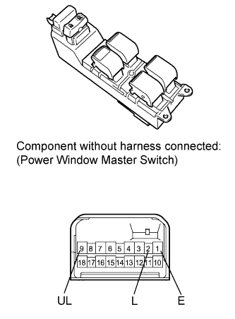
| 5.INSPECT DOOR CONTROL SWITCH ASSEMBLY (DRIVER SIDE) |
w/ Power Window:
Remove the power window master switch (COROLLA_ZRE142 RM000001P7X03GX.html).
Measure the resistance according to the value(s) in the table below.
- Standard Resistance:
Tester Connection
| Switch Condition
| Specified Condition
|
1 (E) - 2 (L)
| Lock
| Below 1 Ω
|
1 (E) - 2 (L)
1 (E) - 9 (UL)
| OFF (Free)
| 10 kΩ or higher
|
1 (E) - 9 (UL)
| Unlock
| Below 1 Ω
|
w/o Power Window: (Except for TMC made)
Remove the door control switch (COROLLA_ZRE142 RM000001P7X03GX.html).
Measure the resistance according to the value(s) in the table below.
- Standard Resistance:
Tester Connection
| Switch Condition
| Specified Condition
|
3 (E) - 4 (L)
| Lock
| Below 1 Ω
|
3 (E) - 4 (L)
2 (UL) - 3 (E)
| OFF (Free)
| 10 kΩ or higher
|
2 (UL) - 3 (E)
| Unlock
| Below 1 Ω
|
- Result:
Result
| Proceed to
|
OK
| A
|
NG (for Driver Side with Power Window)
| B
|
NG (for Driver Side without Power Window)
| C
|
| 6.CHECK HARNESS AND CONNECTOR (JUNCTION BLOCK - DOOR CONTROL SWITCH (DRIVER SIDE)) |
Disconnect the 2H junction block connector.
w/ Power Window: (Except for TMC made)
Disconnect the I3 switch connector.
Measure the resistance according to the value(s) in the table below.
- Standard Resistance:
Tester Connection
| Condition
| Specified Condition
|
I3-2 (L) - 2H-4 (L1)
| Always
| Below 1 Ω
|
I3-9 (UL) - 2H-5 (UL1)
| Always
| Below 1 Ω
|
I3-1 (E) - Body ground
| Always
| Below 1 Ω
|
I3-2 (L) - Body ground
| Always
| 10 kΩ or higher
|
I3-9 (UL) - Body ground
| Always
| 10 kΩ or higher
|
w/o Power Window: (Except for TMC made)
Disconnect the 2H J/B connector.
Measure the resistance according to the value(s) in the table below.
- Standard Resistance:
Tester Connection
| Condition
| Specified Condition
|
I8-4 (L) - 2H-4 (L1)
| Always
| Below 1 Ω
|
I8-2 (UL) - 2H-5 (UL1)
| Always
| Below 1 Ω
|
I8-3 (E) - Body ground
| Always
| Below 1 Ω
|
I8-4 (L) - Body ground
| Always
| 10 kΩ or higher
|
I8-2 (UL) - Body ground
| Always
| 10 kΩ or higher
|
w/ Power Window: (for TMC made)
Disconnect the I3 switch connector.
Measure the resistance according to the value(s) in the table below.
- Standard Resistance:
Tester Connection
| Condition
| Specified Condition
|
I3-2 (L) - 2H-13 (L1)
| Always
| Below 1 Ω
|
I3-9 (UL) - 2H-14 (UL1)
| Always
| Below 1 Ω
|
I3-1 (E) - Body ground
| Always
| Below 1 Ω
|
I3-2 (L) - Body ground
| Always
| 10 kΩ or higher
|
I3-9 (UL) - Body ground
| Always
| 10 kΩ or higher
|
| | REPAIR OR REPLACE HARNESS OR CONNECTOR |
|
|
| OK |
|
|
|
| REPLACE MAIN BODY ECU (INSTRUMENT PANEL JUNCTION BLOCK) |
|
| 7.READ VALUE USING TECHSTREAM (DOOR CONTROL SWITCH (PASSENGER SIDE)) |
Connect the Techstream
Turn the ignition switch to ON.
Turn the Techstream on.
Enter the following menus: Body Electrical / Main Body / Data List.
Read the Data List according to the display on the Techstream.
Main BodyTester Display
| Measurement Item/Range
| Normal Condition
| Diagnostic Note
|
Door Lock SW-Lock
| Passenger door manual lock switch signal / ON or OFF
| ON: Passenger side door control switch is pushed to lock position
OFF: Passenger side door control switch is released
| -
|
Door Lock SW-Unlock
| Passenger door manual unlock switch signal / ON or OFF
| ON: Passenger side door control switch is pushed to unlock position
OFF: Passenger side door control switch is released
| -
|
- OK:
- The Techstream indicates ON or OFF according to the switch operation as shown in the table above.
| OK |
|
|
|
| REPLACE MAIN BODY ECU (INSTRUMENT PANEL JUNCTION BLOCK) |
|
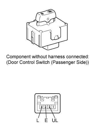
| 8.INSPECT DOOR CONTROL SWITCH ASSEMBLY (PASSENGER SIDE) |
Remove the door control switch (COROLLA_ZRE142 RM000001P7X03GX.html).
Measure the resistance according to the value(s) in the table below.
- Standard Resistance:
Tester Connection
| Switch Condition
| Specified Condition
|
3 (E) - 4 (L)
| Lock
| Below 1 Ω
|
3 (E) - 4 (L)
2 (UL) - 3 (E)
| OFF (Free)
| 10 kΩ or higher
|
2 (UL) - 3 (E)
| Unlock
| Below 1 Ω
|
| 9.CHECK HARNESS AND CONNECTOR (JUNCTION BLOCK - DOOR CONTROL SWITCH (PASSENGER SIDE)) |
Except for TMC made:
Disconnect the 2H junction block connector.
Measure the resistance according to the value(s) in the table below.
- Standard Resistance:
Tester Connection
| Condition
| Specified Condition
|
H9-4 (L) - 2H-13 (L1)
| Always
| Below 1 Ω
|
H9-2 (UL) - 2H-14 (UL1)
| Always
| Below 1 Ω
|
H9-3 (E) - Body ground
| Always
| Below 1 Ω
|
H9-4 (L) - Body ground
| Always
| 10 kΩ or higher
|
H9-2 (UL) - Body ground
| Always
| 10 kΩ or higher
|
for TMC made:
Disconnect the 2H junction block connector.
Measure the resistance according to the value(s) in the table below.
- Standard Resistance:
Tester Connection
| Condition
| Specified Condition
|
H9-4 (L) - 2H-4 (L1)
| Always
| Below 1 Ω
|
H9-2 (UL) - 2H-5 (UL1)
| Always
| Below 1 Ω
|
H9-3 (E) - Body ground
| Always
| Below 1 Ω
|
H9-4 (L) - Body ground
| Always
| 10 kΩ or higher
|
H9-2 (UL) - Body ground
| Always
| 10 kΩ or higher
|
| | REPAIR OR REPLACE HARNESS OR CONNECTOR |
|
|
| OK |
|
|
|
| REPLACE MAIN BODY ECU (INSTRUMENT PANEL JUNCTION BLOCK) |
|
| 10.CHECK DOOR LOCK OPERATION (DOOR KEY CYLINDER) |
Proceed to the next step according to symptom if all the doors cannot be locked/unlocked at once.
- Result:
Result
| Proceed to
|
All doors cannot be locked/unlocked at once by using door key cylinder on driver side.
| A
|
All doors cannot be locked/unlocked at once by using door key cylinder on passenger side.
| B
|
All doors cannot be locked/unlocked at once by using either driver and passenger side door key cylinder.
| C
|
| |
|
| | REPLACE MAIN BODY ECU (INSTRUMENT PANEL JUNCTION BLOCK) |
|
|
| 11.READ VALUE USING TECHSTREAM (DOOR KEY LINKED LOCK AND UNLOCK SWITCH (DRIVER SIDE)) |
Connect the Techstream
Turn the ignition switch to ON.
Turn the Techstream on.
Enter the following menus: Body Electrical / Main Body / Data List.
Read the Data List according to the display on the Techstream.
Main BodyTester Display
| Measurement Item/Range
| Normal Condition
| Diagnostic Note
|
Door Key SW-Lock
| Driver side door key linked lock switch signal/ON or OFF
| ON: Driver side door key cylinder is turned to lock position
OFF: Driver side door key cylinder is not turned
| -
|
D-Door Key SW-UL
| Driver side door key linked unlock switch signal/ON or OFF
| ON: Driver side door key cylinder is turned to unlock position
OFF: Driver side door key cylinder is not turned
| -
|
- OK:
- The Techstream indicates ON or OFF according to the switch operation as shown in the table above.
| OK |
|
|
|
| REPLACE MAIN BODY ECU (INSTRUMENT PANEL JUNCTION BLOCK) |
|
| 12.INSPECT FRONT DOOR LOCK ASSEMBLY (DRIVER SIDE) |
Remove the front door lock assembly (driver side) (COROLLA_ZRE142 RM0000011QF0BBX.html).
Measure the resistance according to the value(s) in the table below.
- Standard Resistance:
Tester Connection
| Condition
| Specified Condition
|
9 (L) - 7 (E)
| ON (Door lock set to LOCK)
| Below 1 Ω
|
9 (L) - 7 (E)
10 (UL) - 7 (E)
| OFF (Free)
| 10 kΩ or higher
|
10 (UL) - 7 (E)
| ON (Door lock set to UNLOCK)
| Below 1 Ω
|
| 13.CHECK HARNESS AND CONNECTOR (FRONT DOOR LOCK - MAIN BODY ECU (INSTRUMENT PANEL J/B)) |
w/ Smart Key System:
Disconnect the 2H junction block connector.
Disconnect the E50 ECU connector.
Measure the resistance according to the value(s) in the table below.
- Standard Resistance:
Tester Connection
| Condition
| Specified Condition
|
I5-9 (L) - 2H-7 (L2)
| Always
| Below 1 Ω
|
I5-10 (UL) - E50-9 (UL3)
| Always
| Below 1 Ω
|
I5-7 (E) - Body ground
| Always
| Below 1 Ω
|
I5-9 (L) - Body ground
| Always
| 10 kΩ or higher
|
I5-10 (UL) - Body ground
| Always
| 10 kΩ or higher
|
w/o Smart Key System:
Disconnect the 2H junction block connector.
Disconnect the E61 ECU connector.
Measure the resistance according to the value(s) in the table below.
- Standard Resistance:
Tester Connection
| Condition
| Specified Condition
|
I5-9 (L) - 2H-7 (L2)
| Always
| Below 1 Ω
|
I5-10 (UL) - E61-14 (UL3)
| Always
| Below 1 Ω
|
I5-7 (E) - Body ground
| Always
| Below 1 Ω
|
I5-9 (L) - Body ground
| Always
| 10 kΩ or higher
|
I5-10 (UL) - Body ground
| Always
| 10 kΩ or higher
|
| | REPAIR OR REPLACE HARNESS OR CONNECTOR |
|
|
| OK |
|
|
|
| REPLACE MAIN BODY ECU (INSTRUMENT PANEL JUNCTION BLOCK) |
|
| 14.READ VALUE USING TECHSTREAM (DOOR KEY LINKED LOCK AND UNLOCK SWITCH (PASSENGER SIDE)) |
Connect the Techstream
Turn the ignition switch to ON.
Turn the Techstream on.
Enter the following menus: Body Electrical / Main Body / Data List.
Read the Data List according to the display on the Techstream.
Main Body ECUTester Display
| Measurement Item/Range
| Normal Condition
| Diagnostic Note
|
Door Key SW-Lock
| Passenger side door key linked lock switch signal/ON or OFF
| ON: Passenger side door key cylinder is turned to lock position
OFF: Passenger side door key cylinder is not turned
| -
|
Door Key SW-Unlock
| Passenger side door key linked unlock switch signal/ON or OFF
| ON: Passenger side door key cylinder is turned to unlock position
OFF: Passenger side door key cylinder is not turned
| -
|
- OK:
- The Techstream indicates ON or OFF according to the switch operation as shown in the table above.
| OK |
|
|
|
| REPLACE MAIN BODY ECU (INSTRUMENT PANEL JUNCTION BLOCK) |
|
| 15.INSPECT FRONT DOOR LOCK ASSEMBLY (PASSENGER SIDE) |
Remove the front door lock assembly (passenger side) (COROLLA_ZRE142 RM0000011QF0BBX.html).
Measure the resistance according to the value(s) in the table below.
- Standard Resistance:
Tester Connection
| Condition
| Specified Condition
|
6 (L) - 8 (E)
| ON (Door lock set to LOCK)
| Below 1 Ω
|
6 (L) - 8 (E)
5 (UL) - 8 (E)
| OFF (Free)
| 10 kΩ or higher
|
5 (UL) - 8 (E)
| ON (Door lock set to UNLOCK)
| Below 1 Ω
|
| 16.CHECK HARNESS AND CONNECTOR (FRONT DOOR LOCK - INSTRUMENT PANEL JUNCTION BLOCK) |
Except for TMC made:
Disconnect the 2H junction block connector.
Measure the resistance according to the value(s) in the table below.
- Standard Resistance:
Tester Connection
| Condition
| Specified Condition
|
H6-6 (L) - 2H-16 (L2)
| Always
| Below 1 Ω
|
H6-5 (UL) - 2H-15 (UL2)
| Always
| Below 1 Ω
|
H6-8 (E) - Body ground
| Always
| Below 1 Ω
|
H6-6 (L) - Body ground
| Always
| 10 kΩ or higher
|
H6-5 (UL) - Body ground
| Always
| 10 kΩ or higher
|
for TMC made:
Disconnect the 2H junction block connector.
Measure the resistance according to the value(s) in the table below.
- Standard Resistance:
Tester Connection
| Condition
| Specified Condition
|
H6-6 (L) - 2H-16 (L2)
| Always
| Below 1 Ω
|
H6-5 (UL) - 2H-6 (UL2)
| Always
| Below 1 Ω
|
H6-8 (E) - Body ground
| Always
| Below 1 Ω
|
H6-6 (L) - Body ground
| Always
| 10 kΩ or higher
|
H6-5 (UL) - Body ground
| Always
| 10 kΩ or higher
|
| | REPAIR OR REPLACE HARNESS OR CONNECTOR |
|
|
| OK |
|
|
|
| REPLACE MAIN BODY ECU (INSTRUMENT PANEL JUNCTION BLOCK) |
|