Navigation System Avc-Lan Circuit
DESCRIPTION
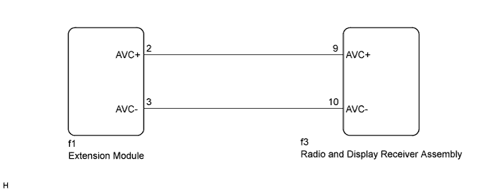
WIRING DIAGRAM
INSPECTION PROCEDURE
INSPECT RADIO AND DISPLAY RECEIVER ASSEMBLY
CHECK HARNESS AND CONNECTOR (AVC-LAN CIRCUIT)
INSPECT MALFUNCTIONING PARTS
NAVIGATION SYSTEM - AVC-LAN Circuit |
DESCRIPTION
Each unit of the navigation system connected to the AVC-LAN (communication bus) transfers the switch signals using the AVC-LAN.If a short to +B or short to ground occurs in the AVC-LAN, the navigation system will not function normally because communication is not possible.
WIRING DIAGRAM
INSPECTION PROCEDURE
- NOTICE:
- After replacing the radio and display receiver assembly of vehicles subscribed to pay-type satellite radio broadcasts, XM radio ID registration is necessary (w/ SDARS System).
- HINT:
- The radio and display receiver assembly is the master unit.
| 1.INSPECT RADIO AND DISPLAY RECEIVER ASSEMBLY |
Disconnect the radio and display receiver assembly connectors.
Measure the resistance according to the value(s) in the table below.
- Standard Resistance:
Tester Connection
| Condition
| Specified Condition
|
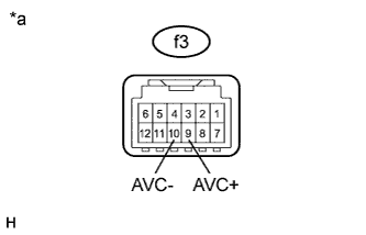
f3-9 (AVC+) - f3-10 (AVC-)
| Always
| 60 to 80 Ω
|
Text in Illustration*a
| Component without harness connected
(Radio and Display Receiver Assembly)
|
| 2.CHECK HARNESS AND CONNECTOR (AVC-LAN CIRCUIT) |
Disconnect the radio and display receiver assembly connector.
Disconnect the extension module connector.
Measure the resistance according to the value(s) in the table below.
- Standard Resistance:
Tester Connection
| Condition
| Specified Condition
|
f3-9 (AVC+) - f1-2 (AVC+)
| Always
| Below 1 Ω
|
f3-10 (AVC-) - f1-3 (AVC-)
| Always
| Below 1 Ω
|
f3-9 (AVC+) - Body ground
| Always
| 10 kΩ or higher
|
f3-10 (AVC-) - Body ground
| Always
| 10 kΩ or higher
|
| | REPAIR OR REPLACE HARNESS OR CONNECTOR |
|
|
| 3.INSPECT MALFUNCTIONING PARTS |
Disconnect and reconnect each slave unit one by one until the master unit returns to normal operation.
- HINT:
- Check all slave units.
- If disconnecting a slave unit causes the master unit to return to normal operation, the slave unit is defective and should be replaced.
- OK:
- Master unit returns to normal operation.
| OK |
|
|
|
| REPLACE MALFUNCTIONING PARTS |
|