Audio And Visual System (W/ Multi-Display With Dvd Player) Reverse Signal Circuit
DESCRIPTION
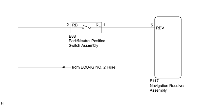
WIRING DIAGRAM
INSPECTION PROCEDURE
INSPECT NAVIGATION RECEIVER ASSEMBLY
CHECK HARNESS AND CONNECTOR (NAVIGATION RECEIVER ASSEMBLY - PARK/NEUTRAL POSITION SWITCH ASSEMBLY)
CHECK HARNESS AND CONNECTOR (PARK/NEUTRAL POSITION SWITCH ASSEMBLY - BATTERY)
AUDIO AND VISUAL SYSTEM (w/ Multi-display with DVD Player) - Reverse Signal Circuit |
DESCRIPTION
The navigation receiver assembly receives a reverse signal from the park/neutral position switch assembly, and then adjusts the vehicle position on the navigation display.
WIRING DIAGRAM
INSPECTION PROCEDURE
| 1.INSPECT NAVIGATION RECEIVER ASSEMBLY |
Disconnect the E117 navigation receiver assembly connector.
Measure the voltage according to the value(s) in the table below.
- Standard Voltage:
Tester Connection
| Condition
| Specified Condition
|
E117-5 (REV) - Body ground
| Ignition switch ON
Shift lever in R
| 11 to 14 V
|
E117-5 (REV) - Body ground
| Ignition switch ON
Shift lever in any position except R
| Below 1 V
|
| 2.CHECK HARNESS AND CONNECTOR (NAVIGATION RECEIVER ASSEMBLY - PARK/NEUTRAL POSITION SWITCH ASSEMBLY) |
Disconnect the E117 navigation receiver assembly connector.
Disconnect the B88 park/neutral position switch assembly connector.
Measure the resistance according to the value(s) in the table below.
- Standard Resistance:
Tester Connection
| Condition
| Specified Condition
|
E117-5 (REV) - B88-1 (RL)
| Always
| Below 1 Ω
|
E117-5 (REV) - Body ground
| Always
| 10 kΩ or higher
|
| | REPAIR OR REPLACE HARNESS OR CONNECTOR |
|
|
| 3.CHECK HARNESS AND CONNECTOR (PARK/NEUTRAL POSITION SWITCH ASSEMBLY - BATTERY) |
Measure the voltage according to the value(s) in the table below.
- Standard Voltage:
Tester Connection
| Condition
| Specified Condition
|
B88-2 (RB) - Body ground
| Ignition switch ON
| 11 to 14 V
|
| | REPAIR OR REPLACE HARNESS OR CONNECTOR |
|
|