Steering Column Assembly Removal
ALIGN FRONT WHEELS FACING STRAIGHT AHEAD
REMOVE STEERING PAD
REMOVE STEERING WHEEL ASSEMBLY
REMOVE LOWER INSTRUMENT PANEL FINISH PANEL SUB-ASSEMBLY
REMOVE LOWER STEERING COLUMN COVER
REMOVE UPPER STEERING COLUMN COVER
REMOVE TURN SIGNAL SWITCH ASSEMBLY WITH SPIRAL CABLE SUB-ASSEMBLY
REMOVE UPPER INSTRUMENT PANEL SUB-ASSEMBLY
REMOVE COLUMN HOLE COVER SILENCER SHEET
SEPARATE NO. 2 STEERING INTERMEDIATE SHAFT ASSEMBLY
REMOVE INSTRUMENT PANEL SUB REINFORCEMENT
REMOVE NO. 3 AIR DUCT SUB-ASSEMBLY
REMOVE TRANSPONDER KEY AMPLIFIER (w/o Smart Key System)
REMOVE STOP LIGHT SWITCH ASSEMBLY
REMOVE STEERING POST ASSEMBLY (for 2ZR-FE)
REMOVE STEERING POST ASSEMBLY (for 2AZ-FE)
REMOVE NO. 2 STEERING INTERMEDIATE SHAFT ASSEMBLY
Steering Column Assembly -- Removal |
| 1. ALIGN FRONT WHEELS FACING STRAIGHT AHEAD |
(COROLLA_ZRE142 RM000000UW80A1X.html)
| 3. REMOVE STEERING WHEEL ASSEMBLY |
for Type A:
Remove the steering wheel assembly set nut.
Text in Illustration*a
| Matchmark
|
Put matchmarks on the steering wheel assembly and steering main shaft.
Disconnect the connectors from the spiral cable sub-assembly.
Using SST, remove the steering wheel assembly.
Text in Illustration*a
| Turn
|
*b
| Hold
|
- SST
- 09950-50013(09951-05010,09952-05010,09953-05020,09954-05070)
- NOTICE:
- Apply a small amount of grease to the threads and tip of SST (09953-05020) before use.
for Type B:
Remove the steering wheel assembly set nut.
Text in Illustration*a
| Matchmark
|
Put matchmarks on the steering wheel assembly and steering main shaft.
Disconnect the connectors from the spiral cable sub-assembly.
Using SST, remove the steering wheel assembly.
Text in Illustration*a
| Turn
|
*b
| Hold
|
- SST
- 09950-50013(09951-05010,09952-05010,09953-05020,09954-05070)
- NOTICE:
- Apply a small amount of grease to the threads and tip of SST (09953-05020) before use.
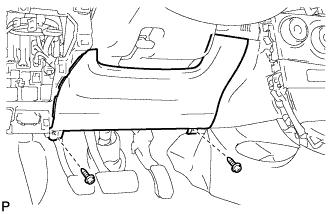
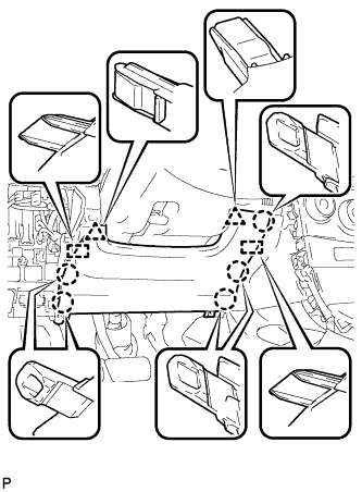
| 4. REMOVE LOWER INSTRUMENT PANEL FINISH PANEL SUB-ASSEMBLY |
Remove the 2 screws <B>.
Disengage the 5 claws, 2 guides and 2 clips, and then remove the lower instrument panel finish panel sub-assembly.
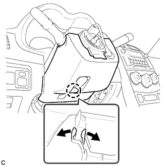
| 5. REMOVE LOWER STEERING COLUMN COVER |
- NOTICE:
- Removing the lower steering column cover in the incorrect order will cause the lower steering column cover to break.
Push the right and left sides of the lower steering column cover, and disengage the 4 claws.
Insert your fingers into the opening of the tilt lever of the lower steering column cover to disengage the claw.
- HINT:
- Spread the claw to disengage it.
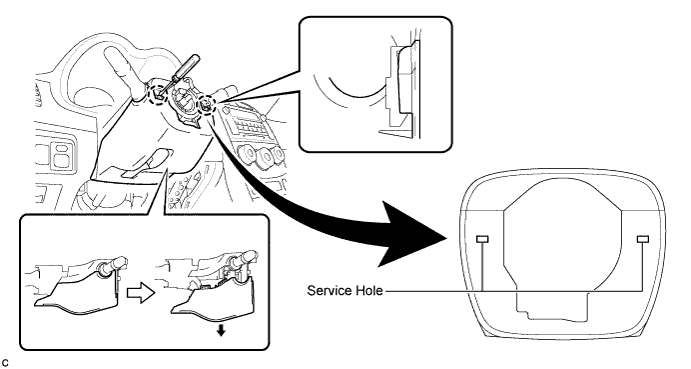
Using a screwdriver, insert the tip into each service hole to disengage the 2 claws and remove the lower steering column cover as shown in the illustration.
| 6. REMOVE UPPER STEERING COLUMN COVER |
Disengage the claw and the 2 pins, and remove the upper steering column cover.
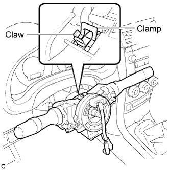
| 7. REMOVE TURN SIGNAL SWITCH ASSEMBLY WITH SPIRAL CABLE SUB-ASSEMBLY |
Disconnect the connectors from the turn signal switch assembly with spiral cable sub-assembly.
Use pliers to hold the clamp and raise the claw with a screwdriver. Remove the turn signal switch assembly with spiral cable sub-assembly from the steering column assembly.
| 8. REMOVE UPPER INSTRUMENT PANEL SUB-ASSEMBLY |
(COROLLA_ZRE142 RM0000024DD08HX.html)
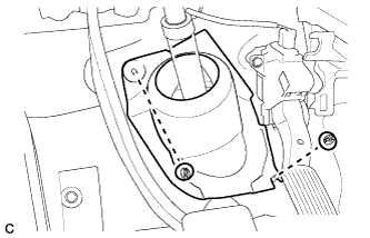
| 9. REMOVE COLUMN HOLE COVER SILENCER SHEET |
Turn back the floor carpet, and remove the 2 clips and column hole cover silencer sheet.
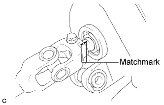
| 10. SEPARATE NO. 2 STEERING INTERMEDIATE SHAFT ASSEMBLY |
Put matchmarks on the No. 2 steering intermediate shaft assembly and the steering intermediate shaft.
Remove the bolt and separate the No. 2 steering intermediate shaft assembly from the steering intermediate shaft.
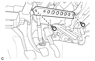
| 11. REMOVE INSTRUMENT PANEL SUB REINFORCEMENT |
Remove the 2 bolts and instrument panel sub reinforcement.
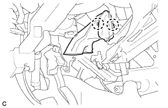
| 12. REMOVE NO. 3 AIR DUCT SUB-ASSEMBLY |
Disengage the 2 claws and remove the No. 3 air duct sub-assembly.
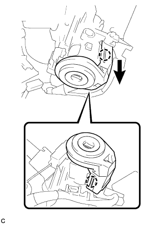
| 13. REMOVE TRANSPONDER KEY AMPLIFIER (w/o Smart Key System) |
Slide the transponder key amplifier to disengage the 2 claws as shown in the illustration.
Disconnect the connector and remove the transponder key amplifier.
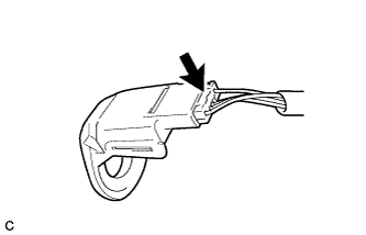
| 14. REMOVE STOP LIGHT SWITCH ASSEMBLY |
Disconnect the connector.
Turn the stop light switch assembly counterclockwise and remove the stop light switch assembly.
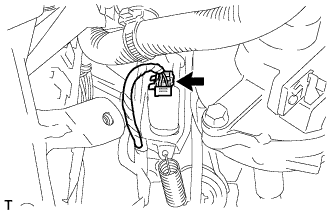
| 15. REMOVE STEERING POST ASSEMBLY (for 2ZR-FE) |
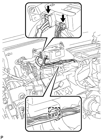
Separate the wire harness clamp from the power steering ECU assembly.
Disconnect the 2 connectors from the power steering ECU assembly.
Disconnect the connectors and disengage the wire harness clamps from the steering column assembly.
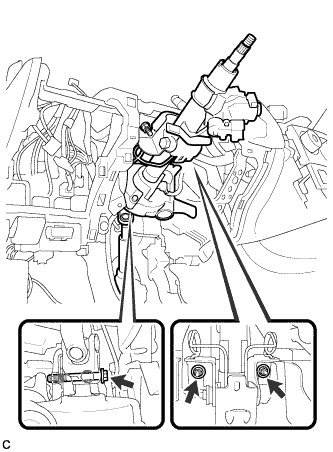
Remove the bolt, 2 nuts and steering post assembly.
- NOTICE:
- Do not release the tilt lever when the steering column assembly is not installed on the vehicle.
- Do not drop or strike the steering column assembly. If dropped or struck, replace it with a new one.
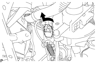
| 16. REMOVE STEERING POST ASSEMBLY (for 2AZ-FE) |
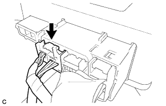
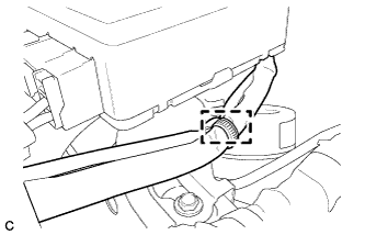
Disconnect the connector from the power steering ECU assembly.
- HINT:
- Pull out the lock of the lock lever, disengage the claw, and turn the lock lever to disconnect the connector, as shown in the illustration.
Disconnect the connector from the power steering ECU assembly.
Separate the wire harness clamp from the power steering ECU assembly.
Remove the bolt, 2 nuts, and steering post assembly.
- NOTICE:
- Do not release the tilt lever when the steering column assembly is not installed on the vehicle.
- Do not drop or strike the steering column assembly. If dropped or struck, replace it with a new one.
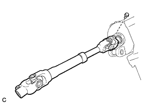
| 17. REMOVE NO. 2 STEERING INTERMEDIATE SHAFT ASSEMBLY |
Put matchmarks on the No. 2 steering intermediate shaft assembly and the steering column assembly.
Remove the bolt and the No. 2 steering intermediate shaft assembly from the steering column assembly.