Brake Pedal -- Installation |
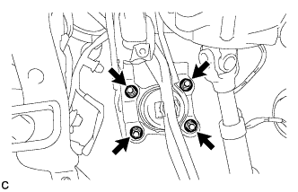
| 1. INSTALL BRAKE PEDAL SUPPORT SUB-ASSEMBLY |
Install the nut to the brake pedal support sub-assembly.
 |
Install the brake pedal support sub-assembly with the 4 nuts.
- Torque:
- 13 N*m{132 kgf*cm, 10 ft.*lbf}
 |
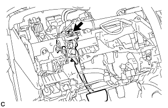
Engage the 2 clamps to the brake pedal support sub-assembly.
 |
Install the brake pedal support sub-assembly to the instrument panel reinforcement with the bolt.
- Torque:
- 24 N*m{245 kgf*cm, 18 ft.*lbf}
 |
| 2. INSTALL STOP LIGHT SWITCH MOUNTING ADJUSTER |
Install the stop light switch mounting adjuster to the brake pedal support sub-assembly.
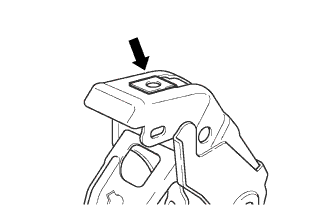
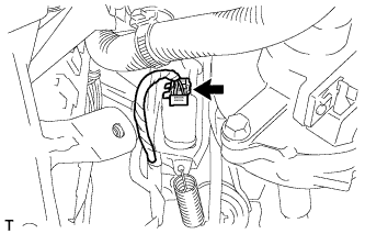
| 3. INSTALL STOP LIGHT SWITCH ASSEMBLY |
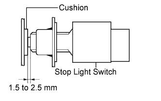
Insert the stop light switch assembly until the rod hits the cushion.
- NOTICE:
- When inserting the stop light switch assembly, support the pedal from behind so that the pedal is not pushed in.
 |
Make a quarter turn clockwise to install the stop light switch assembly.
- Torque:
- 1.5 N*m{15 kgf*cm, 13 in.*lbf}or less
- NOTICE:
- When inserting the stop light switch assembly, support the pedal from behind so that the pedal is not pushed in.
 |
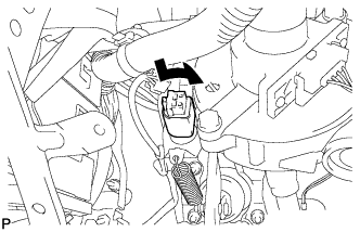
Connect the connector.
 |
Check the protrusion of the rod.
- Protrusion of the rod:
- 1.5 to 2.5 mm (0.059 to 0.098 in.)
- NOTICE:
- Do not depress the brake pedal.
 |
| 4. CONNECT BRAKE MASTER CYLINDER PUSH ROD CLEVIS |
Apply lithium soap base glycol grease to the push rod pin.
 |
Connect the brake master cylinder push rod clevis to the brake pedal with the push rod clevis pin, and install a new clip as shown in the illustration.
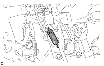
| 5. INSTALL BRAKE PEDAL RETURN SPRING |
Install the brake pedal return spring between the brake pedal support sub-assembly and brake master cylinder push rod clevis.
 |
| 6. INSPECT AND ADJUST BRAKE PEDAL HEIGHT |
Check the brake pedal height.
Turn back the carpet.
Turn back the dash silencer from the slit provided on the dash silencer.
Measure the shortest distance between the brake pedal surface and dash panel.
- Pedal height from floor panel:
- 141.4 to 151.4 mm (5.57 to 5.96 in.)

Adjust the brake pedal height.
Disconnect the stop light switch connector.
Remove the stop light switch assembly.
Loosen the push rod clevis lock nut.
Adjust the brake pedal height by turning the push rod.
Tighten the push rod clevis lock nut.
- Torque:
- 26 N*m{265 kgf*cm, 19 ft.*lbf}
Insert the stop light switch into the adjuster mounting until the switch body touches the brake pedal.
- NOTICE:
- Do not depress the brake pedal.
Adjust the stop light switch (COROLLA_ZRE142 RM000002VPN018X_01_0001.html).
Connect the stop light switch connector.
| 7. INSPECT BRAKE PEDAL FREE PLAY |
Stop the engine. Depress the brake pedal several times until no vacuum is left in the brake booster. Release the brake pedal.
Depress the pedal until a slight resistance is felt. Measure the distance as shown in the illustration.
- Pedal free play:
- 1.0 to 6.0 mm (0.0394 to 0.236 in.)
 |
| 8. INSPECT BRAKE PEDAL RESERVE DISTANCE |
- HINT:
- Measure the distance at the same point used for the brake pedal height inspection.
Release the parking brake lever.
With the engine running, depress the brake pedal and measure the pedal reserve distance as shown in the illustration.
- Pedal Reserve Distance from the Dash Panel at 294 N (30 kgf, 66 lbf):
Specified Condition w/ ABS 81 mm (3.19 in.) w/ VSC 87 mm (3.43 in.)
 |
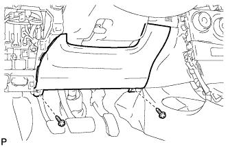
| 9. INSTALL LOWER INSTRUMENT PANEL FINISH PANEL SUB-ASSEMBLY |
Engage the 5 claws, 2 clips and 2 guides.
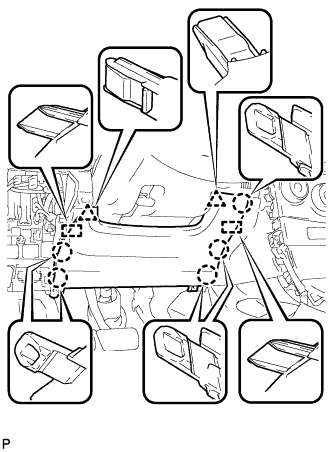 |
Install the lower instrument panel finish panel sub-assembly with the 2 screws <B>.
 |
| 10. INSTALL UPPER INSTRUMENT PANEL SUB-ASSEMBLY |
- HINT:
- Refer to the instructions for Installation of the upper instrument panel sub-assembly (Link).