Lexus IS250 IS220d GSE20 ALE20 - SUSPENSION
REAR UPPER NO. 1 CONTROL ARM - INSTALLATION
| 1. TEMPORARILY TIGHTEN REAR UPPER NO. 1 CONTROL ARM |

Temporarily install the rear upper No. 1 control arm with the bolt, nut, and washer.

Temporarily install the rear upper No. 1 control arm with the bolt, nut, and washer.
- NOTICE:
- Push the axle carrier downward.
| 2. TEMPORARILY TIGHTEN REAR SHOCK ABSORBER WITH COIL SPRING |

Temporarily install the rear shock absorber with coil spring with the bolt and nut.
| 3. TEMPORARILY TIGHTEN REAR STABILIZER LINK ASSEMBLY |
Temporarily install the rear stabilizer link assembly and the height control sensor link bracket to the rear No. 2 suspension arm assembly with the bolt and nut.
| 4. STABILIZE SUSPENSION |

Jack up the axle carrier, with a wooden block placed between the jack and axle carrier, to apply a load to the suspension so that the rear drive shaft assembly becomes level.
| 5. FULLY TIGHTEN REAR UPPER NO. 1 CONTROL ARM |

Fully tighten the nut on the rear upper No. 1 control arm assembly.
- Torque:
- 161 N*m{ 1,640 kgf*cm, 119 ft.*lbf}

Using a ball joint lock nut wrench (19 mm), fully tighten the nut on the rear upper No. 1 control arm assembly.
- Torque:
- :
- 161 N*m{ 1,640 kgf*cm, 119 ft.*lbf}
- When using a ball joint lock nut wrench:
- 117 N*m{ 1,192 kgf*cm, 86 ft.*lbf}
| 6. FULLY TIGHTEN REAR SHOCK ABSORBER WITH COIL SPRING |

Fully tighten the bolt (A) holding the rear shock absorber with coil spring.
- Torque:
- 110 N*m{ 1,120 kgf*cm, 81 ft.*lbf}
- NOTICE:
- Turn the bolt while holding the nut.
| 7. FULLY TIGHTEN REAR STABILIZER LINK ASSEMBLY |
Full tighten the nut (B) holding the rear stabilizer link assembly.
- Torque:
- 27 N*m{ 275 kgf*cm, 20 ft.*lbf}
| 8. INSTALL NO. 2 DIFFERENTIAL SUPPORT PROTECTOR |

Install the No. 2 differential support protector with the 2 nuts.
| 9. INSTALL REAR WHEEL |
- Torque:
- 103 N*m{ 1,050 kgf*cm, 76 ft.*lbf}
| 10. INSPECT AND ADJUST REAR WHEEL ALIGNMENT |
| 11. VEHICLE PREPARATION FOR HEADLIGHT AIM ADJUSTMENT |
Prepare the vehicle:
| 12. PREPARATION FOR HEADLIGHT AIMING |

Prepare the vehicle according to the following conditions:
- NOTICE:
- A distance of 25 m (82 ft) between the vehicle (headlight bulb center) and the wall is necessary for proper aim adjustment. If unavailable, secure a distance of exactly 3 m (9.84 ft) for check and adjustment. (The target zone will change with the distance, so follow the instructions in the illustration.)
Prepare a piece of thick white paper (approximately 2 m (6.6 ft) (height) x 4 m (13.1 ft) (width)) to use as a screen.
Draw a vertical line down the center of screen (V line).
Set the screen as shown in the illustration.

- HINT:
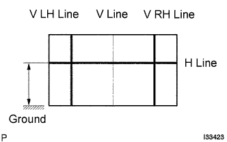
Draw base lines (H line, V LH, V RH lines) on the screen as shown in the illustration.
- HINT:
H Line (Headlight height):
Draw a horizontal line across the screen so that it passes through the center marks. The H line should be at the same height as the headlight bulb center marks of the low-beam headlights.
V LH Line, V RH Line (Center mark position of left-hand (LH) and right-hand (RH) headlights):
Draw two vertical lines so that they intersect the H line at each center mark (aligned with the center of the low-beam headlight bulbs).
| 13. HEADLIGHT AIMING INSPECTION |
Cover the headlight or disconnect the connector of the headlight on the opposite side to prevent light from the headlight not being inspected from affecting headlight aiming inspection.
- NOTICE:
- Do not keep the headlight covered for more than 3 minutes. The headlight lens is made of synthetic resin, and may easily melt or be damaged due to heat.
- HINT:
- When checking the aim of the high-beam, cover the low-beam or disconnect the connector.
Start the engine.
Turn on the headlight and make sure that the cutoff line falls within the specified area, as shown in the illustration.

- HINT:
The cutoff line is 48 mm (1.88 in.) to 698 mm (27.48 in.) below the H line with low-beam (ECE Reg.48).
The cutoff line is 6 mm (0.23 in.) to 84 mm (3.3 in.) below the H line with low-beam (ECE Reg.48).
The cutoff line is 249 mm (9.8 in.) below the H line with low-beam.
The cutoff line is 30 mm (1.18 in.) below the H line with low-beam.
| 14. HEADLIGHT AIMING ADJUSTMENT |

Adjust the aim vertically:
Adjust the headlight aim into the specified range by turning aiming screw A with a screwdriver.
- NOTICE:
- The final turn of the aiming screw should be made in the clockwise direction. If the screw is tightened excessively, loosen it and then retighten it, so that the final turn of the screw is in the clockwise direction.
- HINT:

Adjust the aim horizontally:
Adjust the headlight aim into the specified range by turning aiming screw B with a screwdriver.
- NOTICE:
- The final turn of the aiming screw should be made in the clockwise direction. If the screw is tightened excessively, loosen it and then retighten it, so that the final turn of the screw is in the clockwise direction.
- HINT:
- Perform low-beam aim adjustment.