Brake. Corolla. Zre142 Aze141
DESCRIPTION
WIRING DIAGRAM
INSPECTION PROCEDURE
CHECK HARNESS AND CONNECTOR (MOMENTARY INTERRUPTION)
REPAIR OR REPLACE HARNESS OR CONNECTOR (SKID CONTROL ECU - FRONT SPEED SENSOR)
RECONFIRM DTC
READ VALUE USING TECHSTREAM (FRONT SPEED SENSOR)
PERFORM TEST MODE (SIGNAL CHECK)
RECONFIRM DTC
CHECK FRONT SPEED SENSOR INSTALLATION
CHECK FRONT SPEED SENSOR TIP
INSPECT FRONT SPEED SENSOR
CHECK HARNESS AND CONNECTOR (SKID CONTROL ECU - FRONT SPEED SENSOR)
INSPECT SKID CONTROL ECU (SENSOR INPUT)
RECONFIRM DTC
REPLACE FRONT SPEED SENSOR
RECONFIRM DTC
REPLACE FRONT SPEED SENSOR ROTOR
RECONFIRM DTC
DTC C0200/31 Front Speed Sensor RH Circuit |
DTC C0205/32 Front Speed Sensor LH Circuit |
DTC C1271/71 Low Output Signal of Front Speed Sensor RH (Test Mode DTC) |
DTC C1272/72 Low Output Signal of Front Speed Sensor LH (Test Mode DTC) |
DESCRIPTION
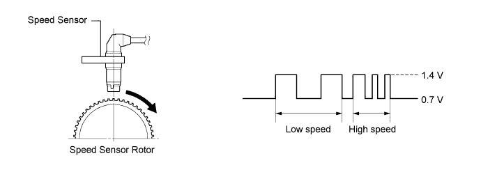
The speed sensor detects the wheel speed and sends the appropriate signals to the skid control ECU. These signals are used for the ABS control system.Speed sensor rotors have 48 serrations. The hall IC type speed sensor use the frequency of output pulses to detect the vehicle speed. Because the sensor outputs digital pulses, it can detect vehicle speeds even when the vehicle is nearly stationary.DTCs C1271/71 and C1272/72 will be deleted when the speed sensor sends a vehicle speed signal or when Test Mode ends. DTCs C1271/71 and C1272/72 are output only in Test Mode.DTC Code
| DTC Detection Condition
| Trouble Area
|
C0200/31
C0205/32
| Any of the following is detected:
- At a vehicle speed of 10 km/h (6 mph) or more, an open or short in the sensor signal circuit continues for 1 second or more.
- Momentary interruptions of the sensor signal from the abnormal wheel occurs 255 times or more.
- An open in the speed sensor signal circuit continues for 0.5 seconds or more.
- With the IG1 terminal voltage 9.5 V or more, the sensor power supply voltage decreases for 0.5 seconds or more.
| - Front speed sensor RH/LH
- Speed sensor circuit
- Speed sensor rotor
- Sensor installation
- Brake actuator assembly (Skid control ECU)
|
C1271/71
C1272/72
| Detected only during Test Mode.
| - Front speed sensor RH/LH
- Sensor installation
- Speed sensor rotor
|
- HINT:
- DTCs C0200/31 and C1271/71 are for the front speed sensor RH.
- DTCs C0205/32 and C1272/72 are for the front speed sensor LH.
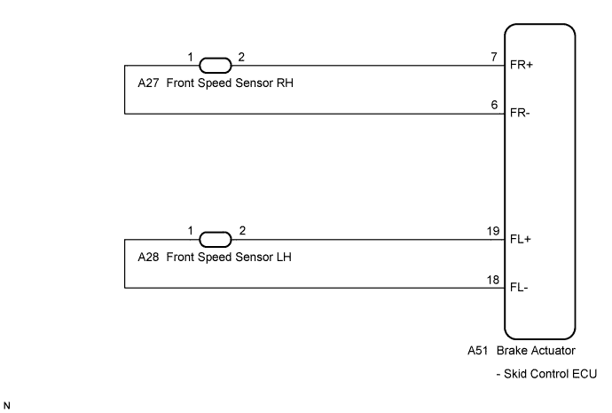
WIRING DIAGRAM
INSPECTION PROCEDURE
| 1.CHECK HARNESS AND CONNECTOR (MOMENTARY INTERRUPTION) |
Using the Techstream, check for any momentary interruptions in the wire harness and connector corresponding to a DTC (COROLLA_ZRE142 RM000000XHS0CKX.html).
ABS/VSC/TRACTester Display
| Measurement Item / Range
| Normal Condition
| Diagnostic Note
|
FR Speed Open
| FR speed sensor open detection / ERROR or NORMAL
| ERROR: Momentary interruption
NORMAL: Normal
| -
|
FL Speed Open
| FL speed sensor open detection / ERROR or NORMAL
| ERROR: Momentary interruption
NORMAL: Normal
| -
|
- Result:
Result
| Proceed to
|
There are momentary interruptions
| A
|
There are no momentary interruptions
| B
|
There is a constant open circuit
| C
|
- HINT:
- Perform the above inspection before removing the sensor and connector.
| 2.REPAIR OR REPLACE HARNESS OR CONNECTOR (SKID CONTROL ECU - FRONT SPEED SENSOR) |
Turn the ignition switch off.
Repair or replace the harness or connector.
Check for any momentary interruptions between the skid control ECU and front speed sensor (COROLLA_ZRE142 RM000000XHS0CKX.html).
Check that there are no momentary interruptions.
Turn the ignition switch off.
Clear the DTCs (COROLLA_ZRE142 RM000000XHV0F3X.html).
Start the engine.
Drive the vehicle at a speed of 40 km/h (25 mph) or more for at least 60 seconds.
Check if the same DTC is recorded (COROLLA_ZRE142 RM000000XHV0F3X.html).
- Result:
Result
| Proceed to
|
DTCs (C0200/31 and/or C0205/32) are output
| A
|
DTCs (C0200/31 and C0205/32) are not output
| B
|
- HINT:
- If troubleshooting has been carried out according to the Problem Symptoms Table, refer back to the table and proceed to the next step (COROLLA_ZRE142 RM000000XHN0DVX.html).
| 4.READ VALUE USING TECHSTREAM (FRONT SPEED SENSOR) |
Turn the ignition switch off.
Connect the Techstream to the DLC3.
Start the engine.
Select Data List mode on the Techstream (COROLLA_ZRE142 RM000000XHW0BZX.html).
ABS/VSC/TRACTester Display
| Measurement Item / Range
| Normal Condition
| Diagnostic Note
|
FR Wheel Speed
| FR wheel speed sensor reading / min.: 0 km/h (0 mph), max.: 326.4 km/h (202 mph)
| Actual wheel speed
| Similar speed as indicated on speedometer
|
FL Wheel Speed
| FL wheel speed sensor reading /min.: 0 km/h (0 mph), max.: 326.4 km/h (202 mph)
| Actual wheel speed
| Similar speed as indicated on speedometer
|
Check that there is no difference between the speed value output from the speed sensor displayed on the Techstream and the speed value displayed on the speedometer when driving the vehicle.
- HINT:
- Factors that affect the indicated vehicle speed include tire size, tire inflation, and tire wear. The speed indicated on the speedometer has an allowable margin of error. This can be tested using a speedometer tester (calibrated chassis dynamometer). For details about testing and the margin of error, see the reference chart (COROLLA_ZRE142 RM0000014WB08AX.html).
- OK:
- The speed value output from the speed sensor displayed on the Techstream is the same as the actual vehicle speed measured using a speedometer tester (calibrated chassis dynamometer).
| 5.PERFORM TEST MODE (SIGNAL CHECK) |
Turn the ignition switch off.
Perform the sensor check in the Test Mode procedure (COROLLA_ZRE142 RM000001JBD052X.html).
- OK:
- All Test Mode DTCs are cleared.
Turn the ignition switch off.
Clear the DTCs (COROLLA_ZRE142 RM000000XHV0F3X.html).
Start the engine.
Drive the vehicle at a speed of 40 km/h (25 mph) or more for at least 60 seconds.
Check if the same DTC is recorded (COROLLA_ZRE142 RM000000XHV0F3X.html).
- Result:
Result
| Proceed to
|
DTCs (C0200/31 and C0205/32) are not output
| A
|
DTCs (C0200/31 and/or C0205/32) are output
| B
|
- HINT:
- If troubleshooting has been carried out according to the Problem Symptoms Table, refer back to the table and proceed to the next step (COROLLA_ZRE142 RM000000XHN0DVX.html).
| 7.CHECK FRONT SPEED SENSOR INSTALLATION |
Turn the ignition switch off.
Check the speed sensor installation.
- OK:
- There is no clearance between the sensor and the front steering knuckle.
- The installation nut is tightened properly.
- Torque:
- 8.5 N*m (87 kgf*cm, 75 in.*lbf)
| 8.CHECK FRONT SPEED SENSOR TIP |
Remove the front speed sensor (COROLLA_ZRE142 RM000002VPG01IX.html).
Check the speed sensor tip.
- OK:
- No scratches or foreign matter on the sensor tip.
- NOTICE:
- Check the speed sensor signal after cleaning or replacement (COROLLA_ZRE142 RM000001JBD052X.html).
| | CLEAN OR REPLACE FRONT SPEED SENSOR |
|
|
| 9.INSPECT FRONT SPEED SENSOR |
Install the front speed sensor.
Make sure that there is no looseness at the locking part and the connecting part of the connectors.
Disconnect the front speed sensor connector.
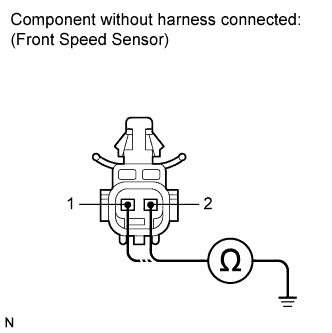
Measure the resistance according to the value(s) in the table below.
- Standard Resistance:
- for RH:
Tester Connection
| Condition
| Specified Condition
|
2 (FR+) - Body ground
| Always
| 10 kΩ or higher
|
1 (FR-) - Body ground
| Always
| 10 kΩ or higher
|
- for LH:
Tester Connection
| Condition
| Specified Condition
|
2 (FL+) - Body ground
| Always
| 10 kΩ or higher
|
1 (FL-) - Body ground
| Always
| 10 kΩ or higher
|
- NOTICE:
- Check the speed sensor signal after replacement (COROLLA_ZRE142 RM000001JBD052X.html).
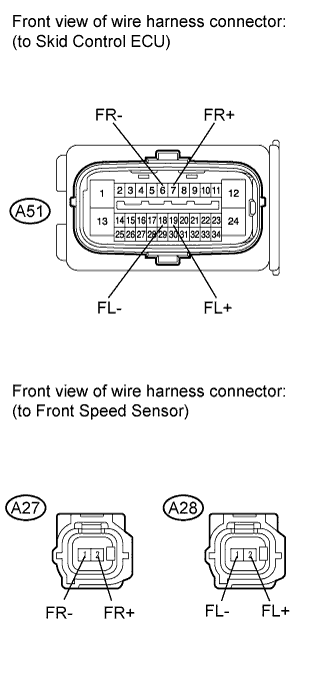
| 10.CHECK HARNESS AND CONNECTOR (SKID CONTROL ECU - FRONT SPEED SENSOR) |
Disconnect the skid control ECU connector.
Measure the resistance according to the value(s) in the table below.
- Standard Resistance:
- for RH:
Tester Connection
| Condition
| Specified Condition
|
A51-7 (FR+) - A27-2 (FR+)
| Always
| Below 1 Ω
|
A51-7 (FR+) - Body ground
| Always
| 10 kΩ or higher
|
A51-6 (FR-) - A27-1 (FR-)
| Always
| Below 1 Ω
|
A51-6 (FR-) - Body ground
| Always
| 10 kΩ or higher
|
- for LH:
Tester Connection
| Condition
| Specified Condition
|
A51-19 (FL+) - A28-2 (FL+)
| Always
| Below 1 Ω
|
A51-19 (FL+) - Body ground
| Always
| 10 kΩ or higher
|
A51-18 (FL-) - A28-1 (FL-)
| Always
| Below 1 Ω
|
A51-18 (FL-) - Body ground
| Always
| 10 kΩ or higher
|
| | REPAIR OR REPLACE HARNESS OR CONNECTOR |
|
|
| 11.INSPECT SKID CONTROL ECU (SENSOR INPUT) |
Reconnect the skid control ECU connector.
Turn the ignition switch to ON.
Measure the voltage according to the value(s) in the table below.
- Standard Voltage:
- for RH:
Tester Connection
| Switch Condition
| Specified Condition
|
A27-2 (FR+) - Body ground
| Ignition switch ON
| 8 to 14 V
|
- for LH:
Tester Connection
| Switch Condition
| Specified Condition
|
A28-2 (FL+) - Body ground
| Ignition switch ON
| 8 to 14 V
|
Turn the ignition switch off.
Reconnect the front speed sensor connector.
Clear the DTCs (COROLLA_ZRE142 RM000000XHV0F3X.html).
Start the engine.
Drive the vehicle at a speed of 40 km/h (25 mph) or more for at least 60 seconds.
Check if the same DTC is recorded (COROLLA_ZRE142 RM000000XHV0F3X.html).
- Result:
Result
| Proceed to
|
DTCs (C0200/31 and/or C0205/32) are output
| A
|
DTCs (C0200/31 and C0205/32) are not output
| B
|
- HINT:
- If troubleshooting has been carried out according to the Problem Symptoms Table, refer back to the table and proceed to the next step (COROLLA_ZRE142 RM000000XHN0DVX.html).
| 13.REPLACE FRONT SPEED SENSOR |
Turn the ignition switch off.
Replace the front speed sensor (COROLLA_ZRE142 RM000002VPG01IX.html).
- NOTICE:
- Check the speed sensor signal after replacement (COROLLA_ZRE142 RM000001JBD052X.html).
Clear the DTCs (COROLLA_ZRE142 RM000000XHV0F3X.html).
Start the engine.
Drive the vehicle at a speed of 40 km/h (25 mph) or more for at least 60 seconds.
Check if the same DTC is recorded (COROLLA_ZRE142 RM000000XHV0F3X.html).
- Result:
Result
| Proceed to
|
DTCs (C0200/31 and/or C0205/32) are output
| A
|
DTCs (C0200/31 and C0205/32) are not output
| B
|
- HINT:
- If troubleshooting has been carried out according to the Problem Symptoms Table, refer back to the table and proceed to the next step (COROLLA_ZRE142 RM000000XHN0DVX.html).
| 15.REPLACE FRONT SPEED SENSOR ROTOR |
Turn the ignition switch off.
Remove the front drive shaft assembly (COROLLA_ZRE142 RM000001HAY03AX.html).
Replace the front axle outboard joint shaft assembly (front speed sensor rotor) (COROLLA_ZRE142 RM000001IWA03MX.html).
- HINT:
- If the front speed sensor rotor needs to be replaced, replace it together with the front axle outboard joint shaft assembly.
- NOTICE:
- Check the speed sensor signal after replacement (COROLLA_ZRE142 RM000001JBD052X.html).
Install the front drive shaft assembly.
Clear the DTCs (COROLLA_ZRE142 RM000000XHV0F3X.html).
Start the engine.
Drive the vehicle at a speed of 40 km/h (25 mph) or more for at least 60 seconds.
Check if the same DTC is recorded (COROLLA_ZRE142 RM000000XHV0F3X.html).
- Result:
Result
| Proceed to
|
DTCs (C0200/31 and C0205/32) are not output
| A
|
DTCs (C0200/31 and/or C0205/32) are output
| B
|
- HINT:
- If troubleshooting has been carried out according to the Problem Symptoms Table, refer back to the table and proceed to the next step (COROLLA_ZRE142 RM000000XHN0DVX.html).