Front Drive Shaft Assembly (For 2Az-Fe) -- Reassembly |
| 1. INSTALL FRONT DRIVE SHAFT BEARING |
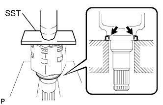
Using SST and a steel plate, install a new front drive shaft bearing.
- SST
- 09527-30010
09527-10011
09630-24014(09620-24051)
 |
Install a new bearing bracket hole snap ring to the front driver shaft assembly RH.
- NOTICE:
- The bearing should be completely installed.
 |
| 2. INSTALL FRONT DRIVE SHAFT DUST COVER (for 2WD) |
Using SST and a press, install a new drive shaft dust cover.
- SST
- 09527-10011
09726-40010
- Distance (A):
- 27.1 mm (1.067 in.)
 |
| 3. INSTALL FRONT DRIVE SHAFT DUST COVER RH (for 2WD) |
Using SST and a press, install a new drive shaft dust cover RH until the distance from the tip of the center drive shaft to the drive shaft dust cover RH meets the specification, as shown in the illustration.
- SST
- 09527-10011
- Distance (A):
- 90.07 to 90.93 mm (3.5460 to 3.5799 in.)
- NOTICE:
- The dust cover should be completely installed.
- Be careful not to damage the dust cover.
 |
| 4. INSTALL FRONT DRIVE SHAFT DUST COVER LH |
Using SST and a press, install a new dust cover into the front drive inboard joint assembly until it is flush with the end.
- SST
- 09527-10011
- NOTICE:
- Install the dust cover in the correct direction.
- Do not deform the dust cover.
 |
| 5. INSTALL OUTBOARD JOINT BOOT |
Wrap the splines of the outboard joint shaft with vinyl tape to prevent the boot from being damaged.
 |
Install new parts onto the outboard joint shaft in the following order.
No. 2 front axle outboard joint boot clamp
Front axle outboard joint boot
Front axle outboard joint boot clamp
Pack the joint portion of the outboard joint shaft and outboard joint boot with grease.
- Standard Quantity:
- 97 to 107 g (3.4 to 3.8 oz.)
Install the outboard joint boot onto the outboard joint shaft groove.
- NOTICE:
- Keep the groove free of grease.
| 6. INSTALL NO. 2 FRONT AXLE OUTBOARD JOINT BOOT CLAMP |
Hold the outboard joint shaft in a vise using aluminum plates.
- NOTICE:
- Do not overtighten the vise.
Place SST onto the boot clamp, press it against the boot and slightly tighten SST.
- SST
- 09521-24010
 |
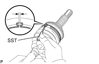
Tighten SST so that the clearance comes within the specified range.
- Standard Clearance:
- 0.5 to 1.5 mm (0.0197 to 0.0591 in.)
Remove SST.
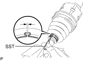
Using SST, measure the clearance of the boot clamp as shown in the illustration.
- SST
- 09240-00020
- Standard Clearance:
- 0.5 to 1.5 mm (0.0197 to 0.0591 in.)
- NOTICE:
- If the clearance is outside the specified range, retighten SST.
 |
| 7. INSTALL FRONT AXLE OUTBOARD JOINT BOOT CLAMP |
Place SST onto the boot clamp, press it against the boot and slightly tighten SST.
- SST
- 09521-24010
 |
Tighten SST so that the clearance comes within the specified range.
- Standard Clearance:
- 0.5 to 1.5 mm (0.0197 to 0.0591 in.)
Remove SST.
Using SST, measure the clearance of the boot clamp as shown in the illustration.
- SST
- 09240-00020
- Standard Clearance:
- 0.5 to 1.5 mm (0.0197 to 0.0591 in.)
- NOTICE:
- If the clearance is outside the specified range, retighten SST.
 |
| 8. INSTALL FRONT DRIVE SHAFT DAMPER |
Install the drive shaft damper onto the front axle outboard shaft assembly as shown in the illustration.
Dimension (A) LH side 210.0 to 214.0 mm (8.27 to 8.43 in.) RH side 213.1 to 217.1 mm (8.39 to 8.55 in.)
 |
| 9. INSTALL FRONT DRIVE SHAFT DAMPER CLAMP |
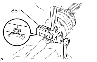
Place SST onto the damper clamp, press it against the boot and slightly tighten SST.
- SST
- 09521-24010
 |
Hold SST and tighten it so that the clearance comes within the specified range.
- Standard Clearance:
- 0.5 to 1.5 mm (0.0197 to 0.0591 in.)
Remove SST.
Using SST, measure the clearance of the damper clamp as shown in the illustration.
- SST
- 09240-00020
- Standard Clearance:
- 0.5 to 1.5 mm (0.0197 to 0.0591 in.)
- NOTICE:
- If the clearance is outside the specified range, retighten SST.
 |
| 10. INSTALL FRONT DRIVE INBOARD JOINT ASSEMBLY |
Install new parts onto the outboard joint shaft in the following order.
Front axle inboard joint boot clamp
Front axle inboard joint boot
No. 2 front axle inboard joint boot clamp
Secure the outboard joint shaft in a vise using aluminum plates.
- NOTICE:
- Do not overtighten the vise.
Remove the protective tape.
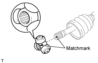
Align the matchmarks and install the tripod joint onto the front axle outboard joint shaft assembly.
- NOTICE:
- Face the serrated side of the tripod joint outward and install it onto the outboard joint end.
 |
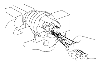
Using a brass bar and hammer, install the tripod joint to the front axle outboard joint shaft assembly.
- NOTICE:
- Do not hit the roller portion.
- Keep the tripod joint free of foreign matter.
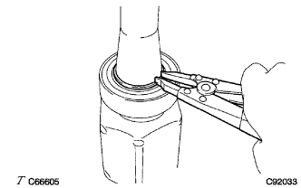
Using a snap ring expander, install a new snap ring to the front axle outboard joint shaft assembly.
 |
Pack the inboard joint with grease.
- Standard Quantity:
- 111 to 121 g (3.9 to 4.3 oz.)
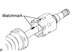
Align the matchmarks and install the inboard joint onto the front axle outboard joint shaft assembly.
 |
| 11. INSTALL INBOARD JOINT BOOT |
Install the inboard joint boot into the grooves of the inboard joint and outboard joint shaft.
- NOTICE:
- Keep the grooves free of grease.
| 12. INSTALL NO. 2 FRONT AXLE INBOARD JOINT BOOT CLAMP |
Place SST onto the boot clamp, press it against the boot and slightly tighten SST.
- SST
- 09521-24010
 |
Tighten SST so that the clearance comes within the specified range.
- Standard Clearance:
- 0.5 to 1.5 mm (0.0197 to 0.0591 in.)
Remove SST.
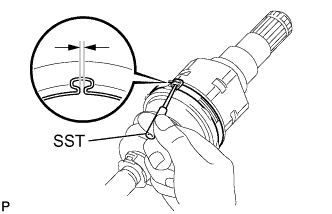
Using SST, measure the clearance of the boot clamp as shown in the illustration.
- SST
- 09240-00020
- Standard Clearance:
- 0.5 to 1.5 mm (0.0197 to 0.0591 in.)
- NOTICE:
- If the clearance is outside the specified range, retighten SST.
 |
| 13. INSTALL FRONT AXLE INBOARD JOINT BOOT CLAMP |
Place SST onto the boot clamp, press it against the boot and slightly tighten SST.
- SST
- 09521-24010
 |
Tighten SST so that the clearance comes within the specified range.
- Standard Clearance:
- 0.5 to 1.5 mm (0.0197 to 0.0591 in.)
Remove SST.
Using SST, measure the clearance of the boot clamp as shown in the illustration.
- SST
- 09240-00020
- Standard Clearance:
- 0.5 to 1.5 mm (0.0197 to 0.0591 in.)
- NOTICE:
- If the clearance is outside the specified range, retighten SST.
 |
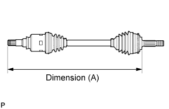
Check whether the drive shaft dimensions are within the following specifications.
Dimension (A) LH side 557.1 mm (1.83 ft.) RH side 873.9 mm (2.87 ft.)
 |
| 14. INSPECT FRONT DRIVE SHAFT |