INSTALL TRANSMISSION OIL FILLER TUBE SUB-ASSEMBLY (for TMC Made)
INSTALL TRANSMISSION OIL FILLER TUBE SUB-ASSEMBLY (except TMC Made)
INSTALL DRIVE PLATE AND TORQUE CONVERTER ASSEMBLY SETTING BOLT
Automatic Transaxle Assembly -- Installation |
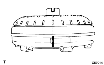
| 1. INSPECT TORQUE CONVERTER ASSEMBLY |
Inspect the one-way clutch.
Set SST so that it fits into the notch of the torque converter assembly hub and the notch of the outer race of the one-way clutch.
- SST
- 09350-32014(09351-32010,09351-32020)
Stand the torque converter assembly up and turn the SST.
Check that it rotates smoothly when turned clockwise and locks up when turned counterclockwise.- SST
- 09350-32014(09351-32010,09351-32020)
Replace the torque converter assembly if the one-way clutch still does not operate as specified.


Determine the condition of the torque converter assembly.
Check that the following conditions are met:
- During the stall test or when the shift lever is in N, metallic sounds are not emitted from the torque converter assembly.
- The one-way clutch turns in one direction and locks in the other direction.
- The amount of powder in the ATF is not greater than the sample shown in the illustration.
- HINT:
- The sample illustration shows approximately 0.25 liters (0.26 US qts, 0.22 Imp. qts) of the ATF taken from a removed torque converter assembly.
- During the stall test or when the shift lever is in N, metallic sounds are not emitted from the torque converter assembly.
 |
Replace the ATF in the torque converter assembly.
If the ATF is discolored and/or has a foul odor, rock the torque converter assembly to move the fluid around inside it. Drain the ATF with the mounting surface of the torque converter assembly facing upward.
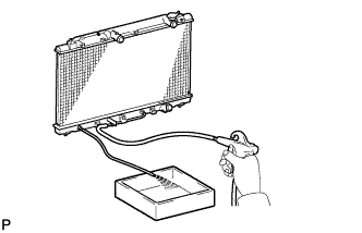
Clean and check the oil cooler and oil pipe line.
If the torque converter assembly is inspected or the ATF is changed, clean the oil cooler and oil pipe line.
- HINT:
- Spray compressed air of 196 kPa (2 kgf/cm2, 28 psi) from the inlet hose.
- If excessive fine powder is found in the ATF, add new ATF using a bucket pump and clean it again.
If the ATF is cloudy, inspect the oil cooler (radiator).
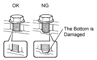
Prevent deformation of the torque converter assembly and damage to the oil pump gear.
When any marks due to interference are found on the end of the bolt for the torque converter assembly and on the bottom of the bolt hole, replace the bolt and the torque converter assembly.
All of the bolts must be the same length.
Washers must be used with the bolts.
 |
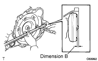
| 2. INSTALL TORQUE CONVERTER ASSEMBLY |
Using a vernier caliper, measure dimension A between the transaxle fitting surface of the engine and the torque converter assembly fitting surface of the drive plate. (#1)
- HINT:
- The ring gear side surface and the torque converter assembly fitting surface are same level.
 |
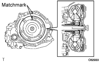
Set the key at the top of the front oil pump drive gear and put a matchmark on the housing.
 |
Put a matchmark on the torque converter assembly so that its groove is clearly indicated.
 |
Align the matchmarks on the case with the one on the torque converter assembly and fit the spline of the input shaft to the spline of the turbine runner.
 |
Rotating the torque converter assembly, fit the spline of the stator shaft with that of the stator.
- HINT:
- Rotate the torque converter assembly approximately 180°.
 |
Rotating the torque converter assembly, align the mark on the case with the one on the torque converter assembly again and fit the key of the oil pump drive gear into the keyway of the torque converter assembly.
- NOTICE:
- Do not push the torque converter assembly excessively when rotating it.
 |
Using a vernier caliper and a straightedge, measure dimension B shown in the illustration and check that dimension B is greater than dimension A, which was measured in step #1.
- Standard:
- A + 1 mm (0.0394 in.) or more
- NOTICE:
- Subtract the thickness of the straightedge from the measured value to gain dimension B.
 |
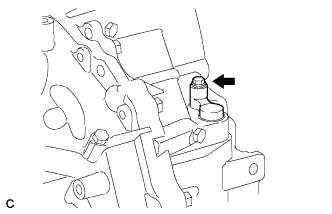
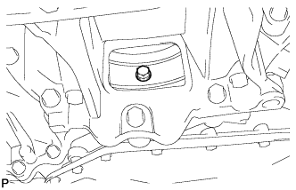
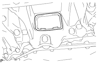
| 3. INSTALL SPEEDOMETER DRIVEN HOLE COVER SUB-ASSEMBLY |
Install the speedometer driven hole cover sub-assembly to the automatic transaxle with the bolt.
- Torque:
- 5.5 N*m{56 kgf*cm, 49 in.*lbf}
 |
| 4. INSTALL TRANSMISSION OIL FILLER TUBE SUB-ASSEMBLY (for TMC Made) |
Apply ATF to a new O-ring, and install it to the transmission oil filler tube sub-assembly.
Install the transmission oil filler tube sub-assembly to the automatic transaxle with the bolt.
- Torque:
- 12 N*m{122 kgf*cm, 9 ft.*lbf}
 |
Install the transmission oil level gauge sub-assembly.
| 5. INSTALL OIL COOLER TUBE SUB-ASSEMBLY (for TMC Made) |
Connect the 2 oil cooler hoses to the 2 unions with the 2 hose clamps.
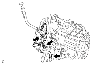 |
Install the oil cooler tube sub-assembly to the automatic transaxle with the bolt.
- Torque:
- 12 N*m{122 kgf*cm, 9 ft.*lbf}
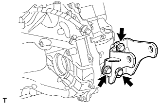
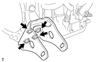
| 6. INSTALL REAR ENGINE MOUNTING BRACKET (for TMC Made) |
Install the rear engine mounting bracket to the automatic transaxle with the 3 bolts.
- Torque:
- Silver Colored Bolt:
- 45 N*m{459 kgf*cm, 33 ft.*lbf}
- Black Colored Bolt:
- 64 N*m{653 kgf*cm, 47 ft.*lbf}
 |
| 7. INSTALL REAR ENGINE MOUNTING BRACKET (except TMC Made) |
Install the rear engine mounting bracket to the automatic transaxle with the 3 bolts.
- Torque:
- 45 N*m{459 kgf*cm, 33 ft.*lbf}
 |
| 8. INSTALL FRONT ENGINE MOUNTING BRACKET |
Install the front engine mounting bracket to the automatic transaxle with the 4 bolts.
- Torque:
- 64 N*m{653 kgf*cm, 47 ft.*lbf}
 |
| 9. INSTALL ENGINE MOUNTING BRACKET LH |
Install the engine mounting bracket LH to the automatic transaxle with the 3 bolts.
- Torque:
- 52 N*m{530 kgf*cm, 38 ft.*lbf}
 |
| 10. INSTALL AUTOMATIC TRANSAXLE ASSEMBLY |
Install the automatic transaxle to the engine with the 7 bolts.
- Torque:
- 30 N*m{301 kgf*cm, 22 ft.*lbf}
- NOTICE:
- Make sure the knock pins are fully engaged and the transaxle securely fitted to the engine before tightening the bolts.
 |
| 11. INSTALL NO. 1 TRANSMISSION CONTROL CABLE BRACKET |
Install the No. 1 transmission control cable bracket to the automatic transaxle with the 2 bolts.
- Torque:
- 12 N*m{122 kgf*cm, 9 ft.*lbf}
 |
Connect the 2 connectors and wire harness clamp.
| 12. INSTALL TRANSMISSION CONTROL CABLE SUPPORT |
Install the transmission control cable support with the bolt.
- Torque:
- 12 N*m{122 kgf*cm, 9 ft.*lbf}
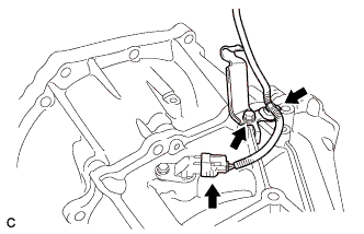 |
Connect the wire harness clamp and speed sensor connector.
| 13. INSTALL STARTER ASSEMBLY |
Install the starter assembly with the 2 bolts.
- Torque:
- 37 N*m{377 kgf*cm, 27 ft.*lbf}
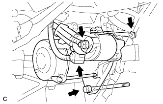 |
Connect the connector.
Connect terminal 30 with the nut.
- Torque:
- 9.8 N*m{100 kgf*cm, 87 in.*lbf}
Close the terminal cap.
| 14. INSTALL TRANSMISSION OIL FILLER TUBE SUB-ASSEMBLY (except TMC Made) |
Apply ATF WS to a new O-ring, and install it to the transmission oil filler tube sub-assembly.
Install the transmission oil filler tube sub-assembly to the automatic transaxle with the bolt.
- Torque:
- 12 N*m{122 kgf*cm, 9 ft.*lbf}
 |
Install the transmission oil level gauge sub-assembly to the transmission oil filler tube sub-assembly.
| 15. INSTALL OIL COOLER TUBE SUB-ASSEMBLY (except TMC Made) |
Connect the 2 oil cooler hoses to the 2 unions with the 2 hose clamps.
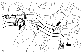 |
Install the oil cooler tube to the automatic transaxle with the bolt.
- Torque:
- 12 N*m{122 kgf*cm, 9 ft.*lbf}
| 16. INSTALL FRONT ENGINE MOUNTING INSULATOR |
Install the front engine mounting insulator with the nut and bolt.
- Torque:
- 73 N*m{744 kgf*cm, 54 ft.*lbf}
 |
| 17. INSTALL REAR ENGINE MOUNTING INSULATOR |
Install the rear engine mounting insulator to the engine mounting bracket with the through bolt.
- Torque:
- except TMC made:
- 65 N*m{663 kgf*cm, 48 ft.*lbf}
- for TMC made:
- 87 N*m{887 kgf*cm, 64 ft.*lbf}
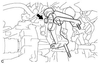 |
| 18. INSTALL DRIVE PLATE AND TORQUE CONVERTER ASSEMBLY SETTING BOLT |
Apply a few drops of adhesive to 2 or 3 threads of the 6 torque converter assembly setting bolts tip.
- Adhesive:
- Toyota Genuine Adhesive 1324, Three Bond 1324 or equivalent
 |
Install the 6 torque converter assembly setting bolts while holding the crankshaft pulley bolt with a wrench.
- Torque:
- 28 N*m{286 kgf*cm, 21 ft.*lbf}
- NOTICE:
- Install the black colored bolt first, and then the silver colored 5 bolts.
 |
| 19. INSTALL FLYWHEEL HOUSING UNDER COVER |
Install the flywheel housing under cover to the automatic transaxle.
 |
| 20. INSTALL ENGINE ASSEMBLY WITH TRANSAXLE |
- HINT:
- See the steps from "Install Engine Assembly with Transaxle" through "Check ABS Speed Sensor Signal" (COROLLA_ZRE142 RM000002WH407RX.html).
| 21. RESET MEMORY |
- HINT:
- Perform Reset Memory (AT initialization) when replacing the automatic transaxle assembly (COROLLA_ZRE142 RM000000W7F0LGX.html).