Oil Pump -- Removal |
| 1. REMOVE ENGINE ASSEMBLY WITH TRANSAXLE |
- HINT:
| 2. INSTALL ENGINE STAND |
Install the engine to an engine stand.
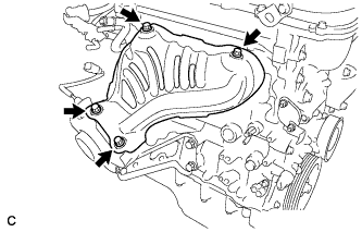
| 3. REMOVE INTAKE MANIFOLD |
Remove the wire harness clamp bracket.
Remove the 2 bolts and disconnect the air tube.
Disconnect the ventilation hose from the intake manifold.
Disconnect the 2 water by-pass hoses.
 |
Disconnect the wire harness clamps from the intake manifold stay.
 |
Remove the 4 bolts and 2 nuts, and remove the intake manifold and intake manifold stay.
Remove the gasket from the intake manifold.
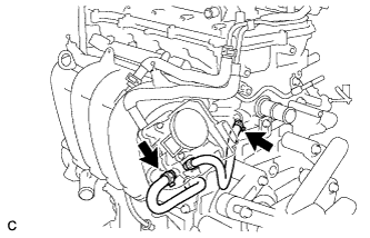
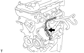
| 4. DISCONNECT FUEL TUBE SUB-ASSEMBLY |
Remove the No. 2 fuel pipe clamp (Type A).
 |
Remove the No. 2 fuel pipe clamp (Type B).
 |
Using SST, disconnect the fuel tube sub-assembly.
- SST
- 09268-21011
 |
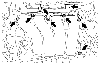
| 5. REMOVE FUEL DELIVERY PIPE SUB-ASSEMBLY |
Remove the bolt and wire harness bracket.
 |
Remove the 2 bolts.
 |
Remove the bolt and the fuel delivery pipe sub-assembly.
 |
Remove the 2 No. 1 delivery pipe spacers.
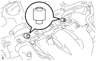 |
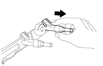
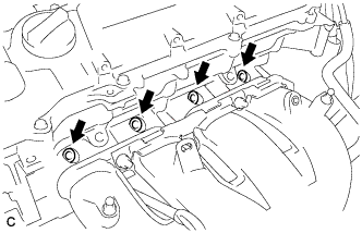
| 6. REMOVE FUEL INJECTOR ASSEMBLY |
Pull the 4 fuel injector assemblies out of the fuel delivery pipe sub-assembly.
 |
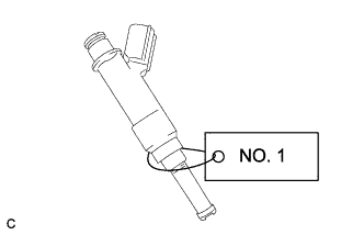
For reinstallation, attach a tag or label to the injector shaft.
- NOTICE:
- Prevent entry of foreign objects by covering the fuel injector with a plastic bag.
 |
Remove the O-rings from the fuel injector assemblies.
Remove the 4 injector vibration insulators.
 |
| 7. REMOVE IGNITION COIL ASSEMBLY |
Remove the 4 bolts and 4 ignition coils.
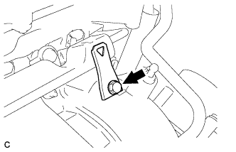
| 8. REMOVE OIL LEVEL DIPSTICK SUB-ASSEMBLY |
Remove the bolt and oil level dipstick.
 |
Remove the O-ring from the oil level dipstick.
| 9. REMOVE NO. 1 EXHAUST MANIFOLD HEAT INSULATOR |
Remove the 4 bolts and No. 1 exhaust manifold heat insulator.
 |
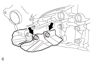
| 10. REMOVE MANIFOLD STAY |
Remove the 2 nuts and 2 drive shaft heat insulator sub-assemblies.
 |
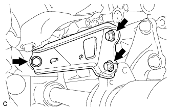
Remove the 3 bolts and manifold stay.
 |
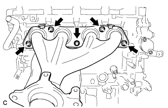
| 11. REMOVE EXHAUST MANIFOLD |
Remove the 5 nuts and exhaust manifold and gasket.
 |
| 12. REMOVE VENTILATION HOSE |
Remove the ventilation hose.
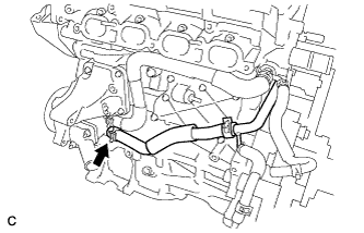
| 13. DISCONNECT NO. 3 WATER BY-PASS HOSE |
Disconnect the No. 3 water by-pass hose from the water inlet housing.
 |
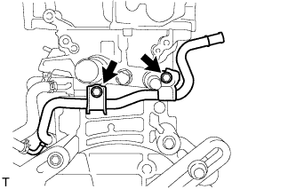
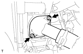
| 14. REMOVE NO. 1 WATER BY-PASS PIPE |
Remove the 2 bolts and No. 1 water by-pass pipe.
 |
| 15. REMOVE WATER BY-PASS HOSE |
Remove the clamp and water by-pass hose.
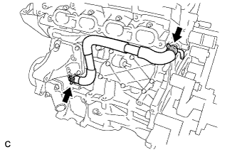
| 16. REMOVE INLET WATER HOSE |
Remove the 2 clamps and inlet water hose.
 |
| 17. REMOVE WATER INLET |
Remove the 2 nuts and water inlet.
 |
| 18. REMOVE THERMOSTAT |
Remove the thermostat.
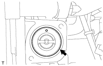 |
Remove the gasket from the thermostat.
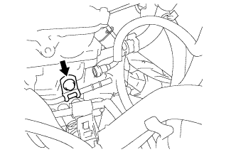
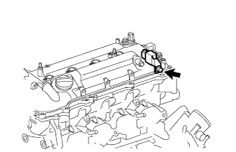
| 19. REMOVE RADIO SETTING CONDENSER |
Remove the bolt and radio setting condenser.
 |
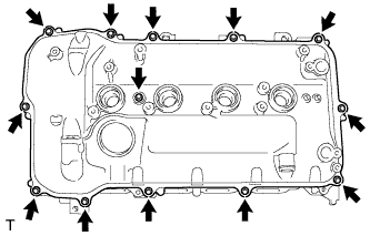
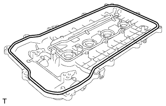
| 20. REMOVE CYLINDER HEAD COVER SUB-ASSEMBLY |
Remove the 13 bolts, seal washer and cylinder head cover.
- NOTICE:
- Be careful not to drop any of the gaskets into the engine when removing the cylinder head cover because the gaskets may stick to the cylinder head cover.
 |
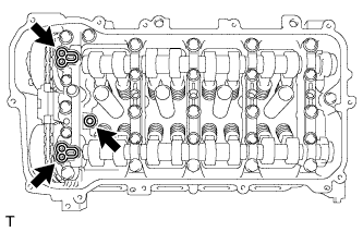
Remove the cylinder head cover gasket.
 |
Remove the 3 gaskets from the camshaft bearing cap.
 |
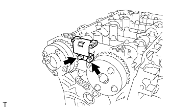
| 21. SET NO. 1 CYLINDER TO TDC/COMPRESSION |
Turn the crankshaft pulley until its groove and the timing mark "0" of the timing chain cover are aligned.
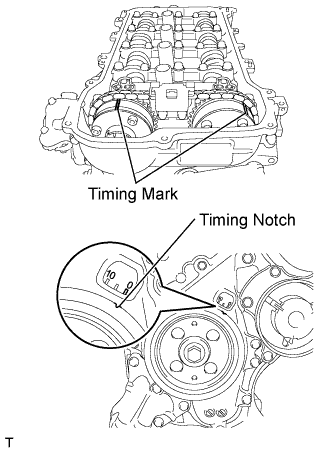 |
Check that each timing mark of the camshaft timing gear and sprocket are aligned with each timing mark located as shown in the illustration. If not, turn the crankshaft 1 revolution (360°) to align the timing marks as shown in the illustration.
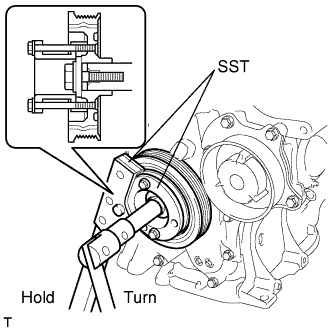
| 22. REMOVE CRANKSHAFT PULLEY |
Using SST, hold the pulley in place and loosen the pulley bolt.
- SST
- 09213-58014(91551-80840)
09330-00021
- NOTICE:
- Check the SST installation positions when installing them to prevent the SST fixing bolts from coming into contact with the timing chain cover sub-assembly.
 |
Using SST, remove the crankshaft pulley and pulley bolt.
- SST
- 09950-50013(09951-05010,09952-05010,09953-05020,09954-05021)
 |
| 23. REMOVE NO. 1 CHAIN TENSIONER ASSEMBLY |
Remove the 2 nuts, bracket, tensioner and gasket.
- NOTICE:
- Do not turn the crankshaft without the chain tensioner installed.
 |
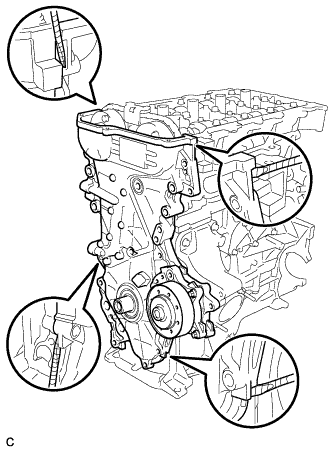
| 24. REMOVE TIMING CHAIN COVER SUB-ASSEMBLY |
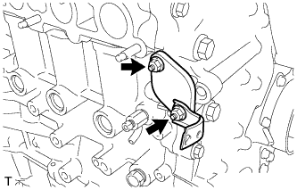
Remove the 3 bolts and engine mounting bracket.
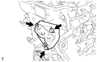 |
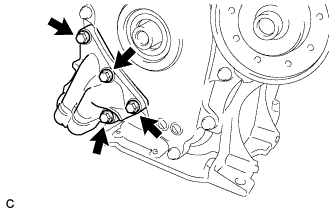
Remove the 4 bolts and oil filter bracket.
 |
Remove the 2 O-rings.
 |
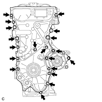
Remove the 19 bolts.
 |
Remove the timing chain cover by prying between the timing chain cover and cylinder head or cylinder block with a screwdriver.
- NOTICE:
- Be careful not to damage the contact surfaces of the timing chain cover, cylinder block, and cylinder head.
- HINT:
- Tape the screwdriver tip before use.
 |
Remove the 3 O-rings.
 |
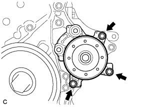
Remove the 3 bolts and water pump.
 |
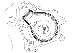
Remove the gasket.
 |
| 25. REMOVE TIMING CHAIN COVER OIL SEAL |
Place the timing chain cover on wooden blocks.
 |
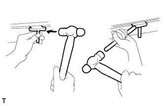
Using a screwdriver and a hammer, pry out the oil seal.
- NOTICE:
- Do not damage the surface of the oil seal press fit hole.
- HINT:
- Tape the screwdriver tip before use.
| 26. REMOVE CHAIN TENSIONER SLIPPER |
Remove the chain tensioner slipper.
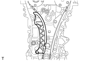 |
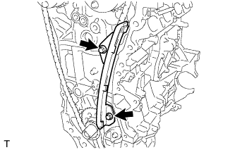
| 27. REMOVE NO. 1 CHAIN VIBRATION DAMPER |
Remove the 2 bolts and No. 1 chain vibration damper.
 |
| 28. REMOVE CHAIN SUB-ASSEMBLY |
Hold the hexagonal portion of the camshaft with a wrench and turn the camshaft timing gear assembly counterclockwise to loosen the chain between the camshaft timing gears.
 |
With the chain loosened, release the chain from the camshaft timing gear assembly and place it on the camshaft timing gear assembly.
- HINT:
- Be sure to release the chain from the sprocket completely.
Turn the camshaft clockwise to return it to the original position and remove the chain.
| 29. REMOVE NO. 2 CHAIN VIBRATION DAMPER |
Remove the 2 bolts and No. 2 chain vibration damper.
 |
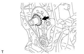
| 30. REMOVE CRANKSHAFT TIMING SPROCKET |
Remove the crankshaft timing sprocket.
 |
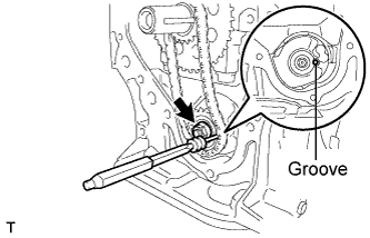
| 31. REMOVE NO. 2 CHAIN SUB-ASSEMBLY |
Temporarily tighten the crank pulley bolt.
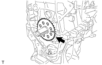
Turn the crankshaft 90° clockwise to align the adjusting hole of the oil pump drive shaft sprocket with the groove of the oil pump.
- NOTICE:
- Do not rotate the crankshaft more than 90°. If the crankshaft is rotated too much without the timing chain installed, the valves may hit the pistons and cause damage.
 |
Remove the crank pulley bolt.
Insert a 3 mm diameter bar into the adjusting hole of the oil pump drive shaft sprocket to lock the gear in position, and then remove the nut.
 |
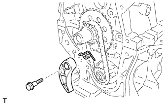
Remove the bolt, chain tensioner plate, and spring.
 |
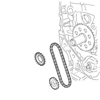
Remove the crankshaft timing sprocket, oil pump drive shaft gear, and No. 2 chain sub-assembly.
 |
| 32. REMOVE NO. 1 CRANKSHAFT POSITION SENSOR PLATE |
Remove the No. 1 crankshaft position sensor plate.
 |
| 33. REMOVE NO. 2 OIL PAN SUB-ASSEMBLY |
Remove the 10 bolts and 2 nuts.
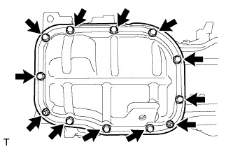 |
Insert the blade of oil pan seal cutter between the crankcase and oil pan. Cut through the sealer and remove the oil pan.
- NOTICE:
- Be careful not to damage the contact surfaces of the crankcase and oil pan.
 |
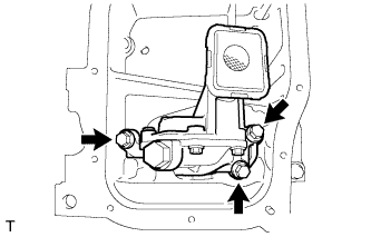
| 34. REMOVE OIL PUMP ASSEMBLY |
Remove the 3 bolts and oil pump.
 |