Water Pump On-Vehicle Inspection
REMOVE NO. 2 CYLINDER HEAD COVER
REMOVE ENGINE UNDER COVER RH
REMOVE V-RIBBED BELT
INSPECT WATER PUMP ASSEMBLY
INSTALL V-RIBBED BELT
ADJUST V-RIBBED BELT
INSPECT V-RIBBED BELT
INSTALL ENGINE UNDER COVER RH
INSTALL NO. 2 CYLINDER HEAD COVER
Water Pump -- On-Vehicle Inspection |
| 1. REMOVE NO. 2 CYLINDER HEAD COVER |
Hold the rear of the cover and raise it to disengage the 2 clips on the rear of the cover. Continue to raise the cover to disengage the 2 clips on the front of the cover to remove the cover.
- NOTICE:
- Attempting to disengage both front and rear clips at the same time may cause the cover to break.
| 2. REMOVE ENGINE UNDER COVER RH |
Loosen bolts A and B.
Loosen bolt C, then remove the V-ribbed belt.
- NOTICE:
- Do not loosen bolt D.
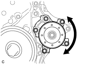
| 4. INSPECT WATER PUMP ASSEMBLY |
Turn the pulley and check that the water pump bearing moves smoothly and quietly.
If necessary, replace the water pump assembly.
Make sure that there are no drops of coolant on the water pump housing.
If necessary, replace the water pump assembly.
Install the belt.
Turn bolt C to adjust the tension of the V-ribbed belt.
Tighten bolts A and B.
- Torque:
- Bolt A:
- 19 N*m{190 kgf*cm, 14 ft.*lbf}
- Bolt B:
- 43 N*m{438 kgf*cm, 32 ft.*lbf}
- NOTICE:
- Confirm that bolt D is not loosened.
Check the belt for wear, cracks or other signs of damage.
If any of the following defects is found, replace the V-ribbed belt.
- The belt is cracked.
- The belt is worn out to the extent that the cords are exposed.
- The belt has chunks missing from the ribs.
Check that the belt fits properly in the ribbed grooves.
- HINT:
- Check with your hand to confirm that the belt has not slipped out of the groove on the bottom of the pulley. If it has slipped out, replace the V-ribbed belt. Install a new V-ribbed belt correctly.

|
Check the V belt deflection and tension.
- Deflection:
Item
| Specified Condition
|
New belt
| 7.0 to 8.2 mm (0.276 to 0.323 in.)
|
Used belt
| 7.6 to 10.0 mm (0.299 to 0.394 in.)
|
- Tension:
Item
| Specified Condition
|
New belt
| 700 to 800 N (71 to 82 kg, 157 to 180 lb)
|
Used belt
| 550 to 750 N (56 to 77 kg, 124 to 169 lb)
|
If the belt deflection is not as specified, adjust it.
- HINT:
- When inspecting the V belt deflection, apply 98 N (10 kgf) tensile force to it.
- After installing a new belt, run the engine for approximately 5 minutes and then readjust the tension to (new belt) specifications.
- Check the V-ribbed belt deflection and tension at the specified point.
- V-ribbed belt tension and deflection should be checked after 2 revolutions of the engine.
- V-ribbed belt tension and deflection should be checked at TDC crank angle and cold condition.
- When adjusting a belt, adjust its deflection and tension to the intermediate values of the specification.
- When reinstalling a belt which has been used for over 5 minutes, adjust its deflection and tension to the used belt specification.
- When using a belt tension gauge, confirm its accuracy by using a master gauge first.
- If using a sonic tension meter:
Input data for sonic tension meter
- Weight:
- 15 g/rib*m
- Width:
- 6 ribs
- Span:
- 188 mm (7.40 in.) (w/ air Conditioning)
- 282 mm (11.1 in.) (w/o air Conditioning)
| 8. INSTALL ENGINE UNDER COVER RH |
| 9. INSTALL NO. 2 CYLINDER HEAD COVER |
Engage the 4 clips to install the No. 2 cylinder head cover.
- NOTICE:
- Be sure to engage the clips securely.
- Do not apply excessive force or do not hit the cover to engage the clips. This may cause the cover to break.