Fuel Injector -- Installation |
| 1. INSTALL FUEL INJECTOR ASSEMBLY |
Install 4 new injector vibration insulators to the 4 fuel injector assemblies.
 |
Install 4 new injector vibration insulators to the 4 fuel injector assemblies.
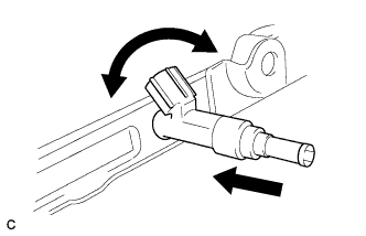
Apply a light coat of gasoline or spindle oil to the contact surfaces of the the O-rings of the fuel injector assemblies.
While turning the fuel injector assembly left and right, install it onto the fuel delivery pipe sub-assembly.
- NOTICE:
- Do not twist the O-ring.
- After installing the fuel injectors, check that they turn smoothly.
 |
| 2. INSTALL NO. 1 DELIVERY PIPE SPACER |
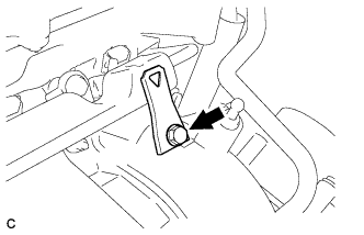
Install the 2 No. 1 delivery pipe spacers onto the cylinder head.
Text in Illustration *a Delivery Pipe Side *b Cylinder Head Side - NOTICE:
- Install the No. 1 delivery pipe spacers in the correct direction.
 |
| 3. INSTALL FUEL DELIVERY PIPE SUB-ASSEMBLY |
Install the fuel delivery pipe sub-assembly with the 4 fuel injector assemblies, then temporarily install the 2 bolts.
- NOTICE:
- Do not drop the fuel injectors when installing the fuel delivery pipe sub-assembly.
- Check that the fuel injector assemblies rotate smoothly after installing the fuel delivery pipe sub-assembly.
 |
Tighten the 2 bolts to the specified torque.
- Torque:
- 21 N*m{214 kgf*cm, 15 ft.*lbf}
|
Install the bolt to secure the fuel delivery pipe sub-assembly.
- Torque:
- 21 N*m{214 kgf*cm, 15 ft.*lbf}
 |
Install the wire harness bracket with the bolt.
- Torque:
- 5.0 N*m{51 kgf*cm, 44 in.*lbf}
 |
| 4. CONNECT FUEL TUBE SUB-ASSEMBLY |
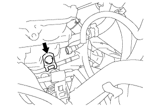
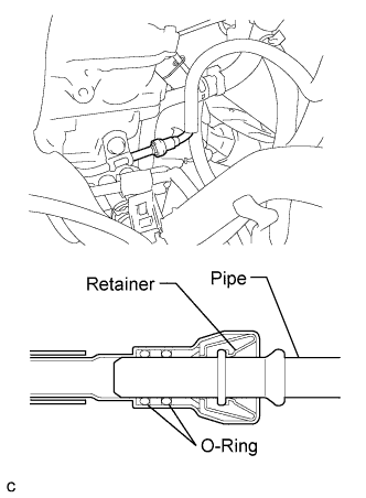
Insert the fuel tube sub-assembly connector into the fuel delivery pipe until a "click" sound can be heard.
- NOTICE:
- Check that there are no scratches or foreign matter around the contact surfaces of the fuel tube connector and pipe before performing this work.
- After connecting the fuel tube, check that the fuel tube connector and pipe are securely connected by pulling on them.
 |
Install a new No. 2 fuel pipe clamp (Type B).
 |
Install a new No. 2 fuel pump clamp (Type A).
 |
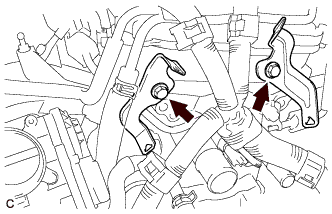
| 5. CONNECT ENGINE WIRE |
Install the 2 wire harness brackets with the 2 bolts.
- Torque:
- 13 N*m{133 kgf*cm, 10 ft.*lbf}
 |
Connect the 4 wire harness clamps.
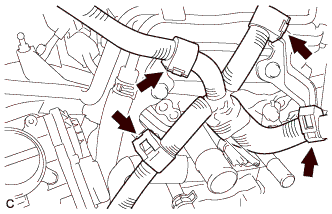 |
Connect the 4 fuel injector assembly connectors.
 |
Connect the 2 wire harness clamps.
Connect the ground wires with the 2 bolts.
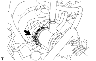
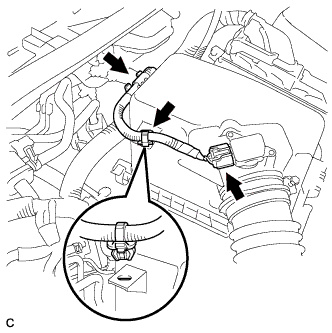
| 6. INSTALL AIR CLEANER CAP SUB-ASSEMBLY |
Install the air cleaner cap sub-assembly with hose with the 2 clamps.
Tighten the hose clamp to the specified torque.
- Torque:
- 2.0 N*m{20 kgf*cm, 18 in.*lbf}
 |
Connect the ventilation hose.
 |
Connect the 2 wire harness clamps and mass air flow meter connector.
 |
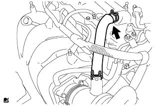
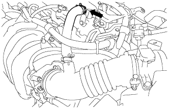
| 7. CONNECT NO. 2 VENTILATION HOSE |
Connect the No. 2 ventilation hose.
 |
| 8. CONNECT CABLE TO NEGATIVE BATTERY TERMINAL |
Connect the cable to the negative battery terminal.
- Torque:
- 5.4 N*m{55 kgf*cm, 48 in.*lbf}
| 9. INSPECT FOR FUEL LEAK |
Check fuel pump operation.
Connect the Techstream to the DLC3.
Turn the ignition switch ON and turn the Techstream on.
- NOTICE:
- Do not start the engine.
Enter the following menus: Powertrain / Engine and ECT / Active Test / Control the Fuel Pump / Speed.
Check for pressure in the fuel inlet tube from the fuel line. Check that sounds of fuel flowing from the fuel tank can be heard. If no sounds can be heard, check the integration relay, fuel pump, ECM and wiring connectors.
Inspect for fuel leaks.
Check that there are no fuel leakage after performing maintenance anywhere on the fuel system. If there is a fuel leak, repair or replace parts as necessary.
Turn the ignition switch off.
Disconnect the Techstream from the DLC3.
| 10. INSTALL NO. 2 CYLINDER HEAD COVER |
Engage the 4 clips to install the No. 2 cylinder head cover.
- NOTICE:
- Be sure to engage the clips securely.
- Do not apply excessive force or do not hit the cover to engage the clips. This may cause the cover to break.
 |