Fuel Injector -- Installation |
| 1. INSTALL FUEL INJECTOR ASSEMBLY |
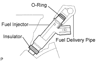
Apply a light coat of gasoline or spindle oil to new O-rings, then install them to the fuel injectors.
 |
Apply a light coat of gasoline or spindle oil to the part of the fuel delivery pipe which comes into contact with the O-ring of the fuel injector.
 |
Apply a light coat of gasoline or spindle oil to the O-ring again, then install the right and left fuel injectors onto the fuel delivery pipe.
- NOTICE:
- Make sure that the O-rings are not cracked or does not jump out of position during installation.
Check that the fuel injectors rotate smoothly. If the fuel injector does not rotate, replace the O-ring.
| 2. INSTALL FUEL DELIVERY PIPE SUB-ASSEMBLY |
Install 4 new insulators to the cylinder head.
 |
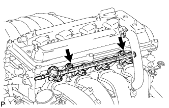
Install the 2 delivery pipe spacers onto the cylinder head.
Install the fuel delivery pipe together with the 4 fuel injectors, then temporarily tighten the 2 bolts.
- NOTICE:
- Be careful not to drop the fuel injectors when installing the fuel delivery pipe.
 |
Check that the fuel injector rotates smoothly.
If the fuel injector does not rotate smoothly, replace the O-ring.
Tighten the 2 bolts to the specified torque.
- Torque:
- 20 N*m{205 kgf*cm, 15 ft.*lbf}
 |
Connect the 4 fuel injector connectors.
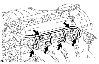 |
Install the 2 wire harness clamps.
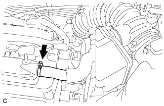
| 3. CONNECT NO. 2 VENTILATION HOSE |
Connect the ventilation hose to the ventilation valve.
- NOTICE:
- Make sure that the paint mark and hose clamp are at the correct angle when installing the hose.
 |
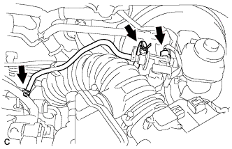
| 4. CONNECT FUEL MAIN TUBE |
Connect the fuel main tube.
Push the fuel tube connector until it makes a "click" sound.
Install the fuel pipe clamp.
Install the fuel tube to the fuel hose clamp.
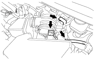
| 5. INSTALL AIR CLEANER CAP SUB-ASSEMBLY WITH HOSE |
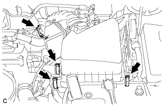
Install the air cleaner cap sub-assembly with hose and lock the 3 clamps.
 |
Tighten the air cleaner hose clamp.
Connect the ventilation hose.
 |
Connect the 2 vacuum hoses and No. 1 vacuum switching valve connector.
 |
Connect the 2 wire harness clamps and the mass air flow meter connector.
 |
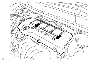
| 6. INSTALL NO. 1 ENGINE COVER SUB-ASSEMBLY |
Install the No. 1 engine cover sub-assembly with the 2 nuts.
 |
| 7. CONNECT CABLE TO NEGATIVE BATTERY TERMINAL |
Connect the cable to the negative battery terminal.
- Torque:
- 5.4 N*m{55 kgf*cm, 48 in.*lbf}
| 8. INSPECT FOR FUEL LEAK |
Check fuel pump operation.
Connect the Techstream to the DLC3.
Turn the ignition switch to ON and turn the Techstream on.
- NOTICE:
- Do not start the engine.
Enter the following menus: Powertrain / Engine and ECT / Active Test / Control the Fuel Pump / Speed.
Check for pressure in the fuel inlet tube from the fuel line. Check that sounds of fuel flowing from the fuel tank can be heard. If no sounds can be heard, check the integration relay, fuel pump, ECM and wiring connectors.
Check for fuel leaks.
There is no fuel leakage after performing maintenance anywhere on the fuel system. If there is a fuel leak, repair or replace parts as necessary.
Turn the ignition switch off.
Disconnect the Techstream from the DLC3.