Cylinder Head Gasket Removal
DISCHARGE FUEL SYSTEM PRESSURE
DISCONNECT CABLE FROM NEGATIVE BATTERY TERMINAL
REMOVE FRONT WIPER ARM HEAD CAP
REMOVE FRONT WIPER ARM AND BLADE ASSEMBLY LH
REMOVE FRONT WIPER ARM AND BLADE ASSEMBLY RH
REMOVE HOOD TO COWL TOP SEAL
REMOVE CENTER NO. 1 COWL TOP VENTILATOR LOUVER
REMOVE COWL TOP VENTILATOR LOUVER LH
REMOVE WINDSHIELD WIPER MOTOR AND LINK ASSEMBLY
REMOVE OUTER COWL TOP PANEL
REMOVE SUSPENSION TOWER DAMPER ASSEMBLY (w/ Front Strut Bar)
REMOVE FRONT WHEEL RH
REMOVE ENGINE UNDER COVER LH
REMOVE ENGINE UNDER COVER RH
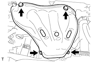
REMOVE NO. 1 ENGINE COVER SUB-ASSEMBLY
DRAIN ENGINE COOLANT
DRAIN ENGINE OIL
REMOVE CENTER EXHAUST PIPE ASSEMBLY
REMOVE FRONT EXHAUST PIPE ASSEMBLY
REMOVE V-RIBBED BELT
REMOVE GENERATOR ASSEMBLY
SEPARATE RADIATOR RESERVE TANK ASSEMBLY
REMOVE AIR CLEANER CAP SUB-ASSEMBLY WITH HOSE
REMOVE THROTTLE BODY ASSEMBLY
REMOVE IGNITION COIL ASSEMBLY
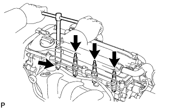
REMOVE SPARK PLUG
REMOVE CYLINDER HEAD COVER SUB-ASSEMBLY
REMOVE ENGINE OIL LEVEL DIPSTICK
REMOVE ENGINE OIL LEVEL DIPSTICK GUIDE
DISCONNECT FUEL MAIN TUBE
REMOVE FUEL DELIVERY PIPE SUB-ASSEMBLY
REMOVE CAMSHAFT TIMING OIL CONTROL VALVE ASSEMBLY
REMOVE INTAKE MANIFOLD
REMOVE NO. 1 INTAKE MANIFOLD INSULATOR
REMOVE MANIFOLD STAY
REMOVE NO. 2 MANIFOLD STAY
REMOVE NO. 1 EXHAUST MANIFOLD HEAT INSULATOR
REMOVE EXHAUST MANIFOLD CONVERTER SUB-ASSEMBLY
REMOVE ENGINE MOUNTING INSULATOR SUB-ASSEMBLY RH
REMOVE IDLER PULLEY SUB-ASSEMBLY
REMOVE OIL PAN SUB-ASSEMBLY
SET NO. 1 CYLINDER TO TDC/COMPRESSION
REMOVE CRANKSHAFT PULLEY
REMOVE NO. 1 CHAIN TENSIONER ASSEMBLY
REMOVE V-RIBBED BELT TENSIONER ASSEMBLY
REMOVE CRANK POSITION SENSOR
REMOVE TIMING CHAIN OR BELT COVER SUB-ASSEMBLY
REMOVE NO. 1 CRANKSHAFT POSITION SENSOR PLATE
REMOVE TIMING CHAIN GUIDE
REMOVE CHAIN TENSIONER SLIPPER
REMOVE NO. 1 CHAIN VIBRATION DAMPER
REMOVE CHAIN SUB-ASSEMBLY
REMOVE CRANKSHAFT TIMING GEAR OR SPROCKET
REMOVE NO. 2 CHAIN SUB-ASSEMBLY
DISCONNECT NO. 1 RADIATOR HOSE
DISCONNECT OUTLET HEATER WATER HOSE
DISCONNECT INLET HEATER WATER HOSE
DISCONNECT ENGINE WIRE
REMOVE NO. 2 CAMSHAFT
REMOVE CAMSHAFT
REMOVE NO. 1 CAMSHAFT BEARING
REMOVE NO. 2 CAMSHAFT BEARING
REMOVE CYLINDER HEAD SUB-ASSEMBLY
REMOVE CYLINDER HEAD GASKET
Cylinder Head Gasket -- Removal |
| 1. DISCHARGE FUEL SYSTEM PRESSURE |
- HINT:
- COROLLA_ZRE142 RM000001EEY04YX.html
| 2. DISCONNECT CABLE FROM NEGATIVE BATTERY TERMINAL |
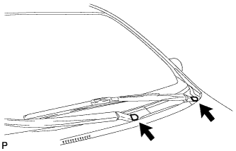
| 3. REMOVE FRONT WIPER ARM HEAD CAP |
Remove the 2 front wiper arm head caps.
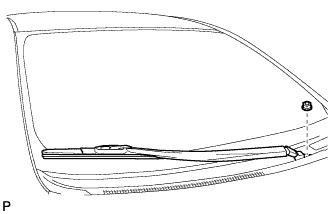
| 4. REMOVE FRONT WIPER ARM AND BLADE ASSEMBLY LH |
Remove the nut and the front wiper arm and blade assembly LH.
| 5. REMOVE FRONT WIPER ARM AND BLADE ASSEMBLY RH |
Remove the nut and the front wiper arm and blade assembly RH.
| 6. REMOVE HOOD TO COWL TOP SEAL |
Disengage the 7 clips and remove the hood to cowl top seal.
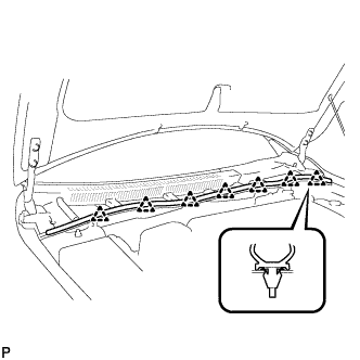
| 7. REMOVE CENTER NO. 1 COWL TOP VENTILATOR LOUVER |
Disengage the clip and 14 claws, and remove the center No. 1 cowl top ventilator louver.
| 8. REMOVE COWL TOP VENTILATOR LOUVER LH |
Disengage the clip and 8 claws, and remove the cowl top ventilator louver LH.
| 9. REMOVE WINDSHIELD WIPER MOTOR AND LINK ASSEMBLY |
Disconnect the connector.
Remove the 2 bolts and the windshield wiper motor and link assembly.
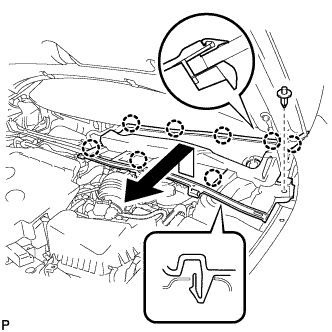
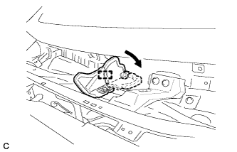
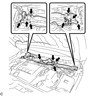
| 10. REMOVE OUTER COWL TOP PANEL |
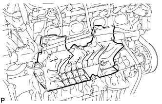
Disengage the clamp and bend the water guard plate RH as shown in the illustration.
Disengage the clamp.
Remove the 12 bolts and outer cowl top panel.
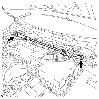
| 11. REMOVE SUSPENSION TOWER DAMPER ASSEMBLY (w/ Front Strut Bar) |
Remove the 2 nuts and suspension tower damper assembly.
| 12. REMOVE FRONT WHEEL RH |
| 13. REMOVE ENGINE UNDER COVER LH |
| 14. REMOVE ENGINE UNDER COVER RH |
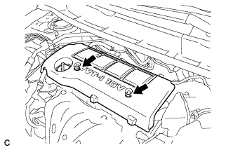
| 15. REMOVE NO. 1 ENGINE COVER SUB-ASSEMBLY |
Remove the 2 nuts and No. 1 engine cover sub-assembly.
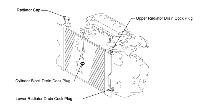
Loosen the lower radiator drain cock plug.
- CAUTION:
- Do not loosen the lower radiator drain cock plug while the engine and radiator are still hot.
- Pressurized, hot engine coolant and steam may be released and cause serious burns.
- HINT:
- Collect the coolant in a container and dispose of it according to the regulations in your area.
Remove the radiator cap.
Loosen the cylinder block drain cock plug.
Remove the oil filler cap.
Remove the oil drain plug and drain the oil into a container.
Clean and install the oil drain plug with a new gasket.
- Torque:
- 25 N*m{255 kgf*cm, 18 ft.*lbf}
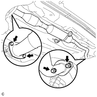
| 18. REMOVE CENTER EXHAUST PIPE ASSEMBLY |
Remove the 4 bolts and 2 compression springs.
Remove the center exhaust pipe assembly from the 2 exhaust pipe supports.
Remove the 2 gaskets.
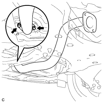
| 19. REMOVE FRONT EXHAUST PIPE ASSEMBLY |
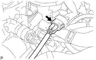
Disconnect the heated oxygen sensor connector.
Remove the 2 bolts, 2 compression springs and front exhaust pipe assembly.
Remove the gasket from the exhaust manifold.
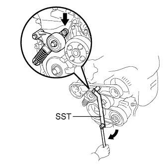
Using SST, slowly turn the V-ribbed belt tensioner clockwise.
- SST
- 09216-42010(09216-04010)
Remove the V-ribbed belt from each pulley and slowly return the tensioner.
- NOTICE:
- Make sure that SST and other tools are set to the tensioner securely.
- When compressing the V-ribbed belt tensioner, slowly turn the tensioner.
- Be careful not to pinch your fingers between the parts.
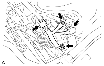
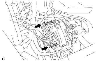
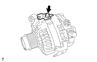
| 21. REMOVE GENERATOR ASSEMBLY |
Disconnect the generator connector.
Remove the nut and disconnect the wire harness from terminal B.
Separate the 2 wire harness clamps.
Remove the 2 bolts and generator assembly.
Remove the bolt and wire harness clamp bracket.
| 22. SEPARATE RADIATOR RESERVE TANK ASSEMBLY |
Remove the 3 bolts and separate the radiator reserve tank assembly.
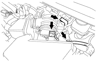
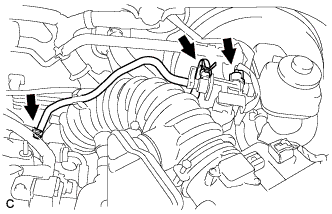
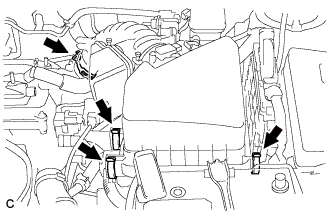
| 23. REMOVE AIR CLEANER CAP SUB-ASSEMBLY WITH HOSE |
Disconnect the mass air flow meter connector.
Separate the 2 wire harness clamps.
Disconnect the No. 1 vacuum switching valve connector and the 2 vacuum hoses.
Disconnect the ventilation hose.
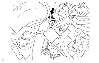
Loosen the No. 1 air cleaner hose clamp, release the 3 air cleaner assembly clamps and remove the air cleaner cap sub-assembly with No. 1 hose.
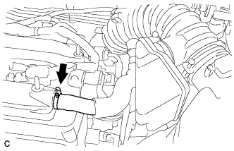
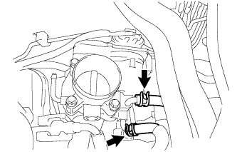
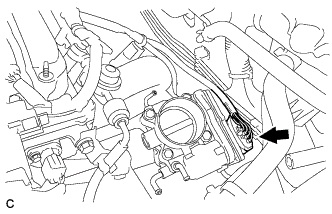
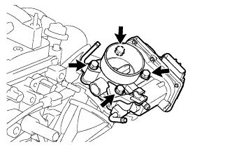
| 24. REMOVE THROTTLE BODY ASSEMBLY |
Disconnect the 2 water by-pass hoses.
Disconnect the throttle body assembly connector.
Remove the 4 bolts and throttle body assembly.
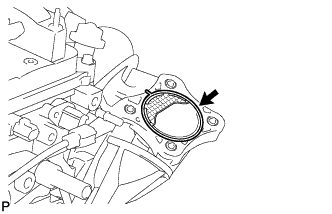
Remove the gasket from the intake manifold.
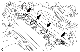
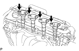
| 25. REMOVE IGNITION COIL ASSEMBLY |
Disconnect the 4 ignition coil connectors.
Remove the 4 bolts and 4 ignition coils.
Remove the 4 spark plugs.
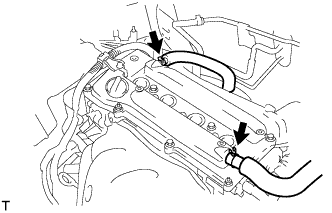
| 27. REMOVE CYLINDER HEAD COVER SUB-ASSEMBLY |
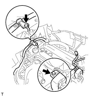
Remove the 2 ventilation hoses from the cylinder head cover sub-assembly.
Remove the 2 bolts and separate the 2 wire harness brackets.
Remove the 8 bolts and 2 nuts, then remove the cylinder head cover sub-assembly and gasket.
| 28. REMOVE ENGINE OIL LEVEL DIPSTICK |
| 29. REMOVE ENGINE OIL LEVEL DIPSTICK GUIDE |
Remove the bolt and engine oil level dipstick guide.
Remove the O-ring from the engine oil level dipstick guide.
| 30. DISCONNECT FUEL MAIN TUBE |
- NOTICE:
- Do not forcibly bend, kink or twist the fuel main tube.
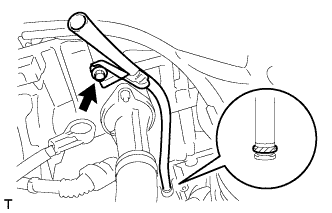
Remove the fuel tube from the fuel hose clamp.
Remove the fuel pipe clamp.
Wipe off any dirt on the fuel tube connector.
Hold the fuel tube connector, and then install SST.
- SST
- 09268-21011
Turn SST to align the retainer inside the fuel tube connector with the chamfered part of SST.
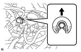
Insert SST into the fuel tube and hold it. Then push the fuel tube connector toward SST.
Mount the retainer of the fuel tube connector onto the chamfered part of SST.
Slide SST and fuel tube connector together towards the fuel tube until they make a "click" sound, and then disconnect the fuel tube.
Drain the fuel remaining inside the fuel tube.
Cover the fuel tube and fuel pipe with a plastic bag to protect the disconnected part.
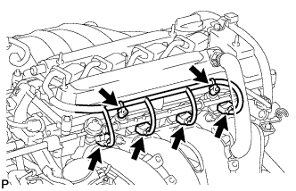
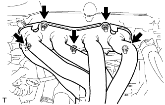
| 31. REMOVE FUEL DELIVERY PIPE SUB-ASSEMBLY |
Remove the 2 wire harness clamps.
Disconnect the 4 fuel injector connectors.
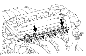
Remove the 2 bolts, then remove the fuel delivery pipe together with the 4 fuel injectors.
- NOTICE:
- Be careful not to drop the fuel injectors when removing the fuel delivery pipe.
Remove the 2 delivery pipe spacers from the cylinder head.
Remove the 4 insulators from the cylinder head.
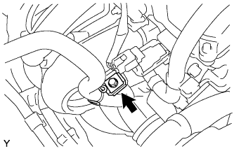
| 32. REMOVE CAMSHAFT TIMING OIL CONTROL VALVE ASSEMBLY |
Remove the bolt and the vacuum hose clamp.
Disconnect the camshaft timing oil control valve connector.
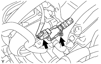
Remove the bolt and the camshaft timing oil control valve assembly.
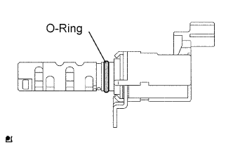
Remove the O-ring from the camshaft timing oil control valve assembly.
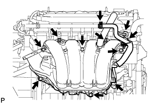
| 33. REMOVE INTAKE MANIFOLD |
Disconnect the union to connector tube hose from the No. 2 hose to hose tube.
Disconnect the camshaft timing oil control valve connector.
Remove the wire harness clamp.
Remove the union to connector tube hose from the vacuum hose clamp.
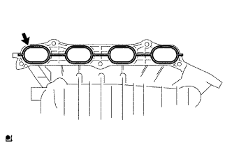
Remove the 5 bolts, 2 nuts and intake manifold.
Remove the gasket from the intake manifold.
| 34. REMOVE NO. 1 INTAKE MANIFOLD INSULATOR |
Remove the No. 1 intake manifold insulator.
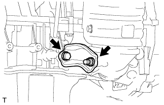
Remove the bolt, nut and manifold stay.
| 36. REMOVE NO. 2 MANIFOLD STAY |
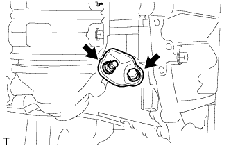
Remove the bolt, nut and No. 2 manifold stay.
| 37. REMOVE NO. 1 EXHAUST MANIFOLD HEAT INSULATOR |
Remove the 4 bolts and No. 1 exhaust manifold heat insulator.
| 38. REMOVE EXHAUST MANIFOLD CONVERTER SUB-ASSEMBLY |
Disconnect the air-fuel ratio sensor connector.
Remove the 5 nuts, exhaust manifold converter sub-assembly and gasket.
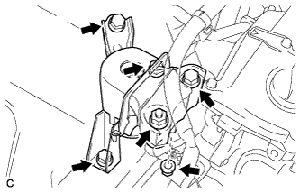
| 39. REMOVE ENGINE MOUNTING INSULATOR SUB-ASSEMBLY RH |
Place a wooden block between a floor jack and the engine, then support the engine using the floor jack.
Remove the 4 bolts and 2 nuts, then remove the engine mounting insulator sub-assembly RH.
- NOTICE:
- Do not apply excessive force to the return tube when removing the engine mounting insulator sub-assembly RH.
- HINT:
- Keep clearance by lowering the engine using the floor jack when removing the front engine mounting insulator.
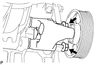
| 40. REMOVE IDLER PULLEY SUB-ASSEMBLY |
Loosen the 2 bolts and remove the idler pulley sub-assembly with the 2 bolts.
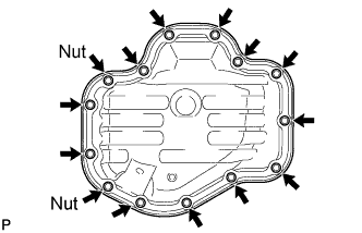
| 41. REMOVE OIL PAN SUB-ASSEMBLY |
Install the No. 1 and No. 2 engine hangers with new bolts.
- Torque:
- 38 N*m{387 kgf*cm, 28 ft.*lbf}
Part No.Item
| Part No.
|
No. 1 engine hanger
| 12281-28010
|
No. 2 engine hanger
| 12282-28010 or 12282-AB010
|
Bolt
| 90080-10177
|
Attach the sling device to the engine hangers and chain block.
Remove the 12 bolts and 2 nuts.
Insert the blade of oil pan seal cutter between the crankcase, chain cover and oil pan, then cut through the applied sealer and remove the oil pan.
- NOTICE:
- Be careful not to damage the contact surface of the crankcase, chain cover or oil pan.
| 42. SET NO. 1 CYLINDER TO TDC/COMPRESSION |
Turn the crankshaft pulley until the groove and the timing mark "0" on the timing chain cover are aligned.
Check that each timing mark on the camshaft timing gear and sprocket is aligned with the timing marks located on the No. 1 and No. 2 bearing caps as shown in the illustration.
If not, turn the crankshaft 1 revolution (360°) to align the timing marks as above.
| 43. REMOVE CRANKSHAFT PULLEY |
Using SST, hold the crankshaft pulley in place and loosen the pulley bolt.
- SST
- 09213-54015(91651-60855)
09330-00021
Using SST, remove the crankshaft pulley.
- SST
- 09950-50013(09951-05010,09952-05010,09953-05020,09954-05021)
09950-40011(09957-04010)
- HINT:
- If necessary, remove the pulley and pulley bolt using SST.
| 44. REMOVE NO. 1 CHAIN TENSIONER ASSEMBLY |
Remove the 2 nuts, No. 1 chain tensioner assembly and gasket.
- NOTICE:
- Do not turn the crankshaft without the No. 1 chain tensioner assembly.
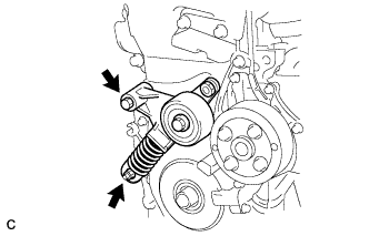
| 45. REMOVE V-RIBBED BELT TENSIONER ASSEMBLY |
Lift the engine upward.
- NOTICE:
- Do not lift the engine more than necessary.
Remove the bolt, nut and V-ribbed belt tensioner assembly.
| 46. REMOVE CRANK POSITION SENSOR |
Disconnect the crank position sensor connector.
Separate the crank position sensor connector clamp and wire harness.
Remove the bolt and crank position sensor.
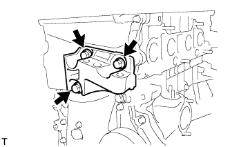
| 47. REMOVE TIMING CHAIN OR BELT COVER SUB-ASSEMBLY |
Remove the 3 bolts and transverse engine engine mounting bracket.
Using an E10 "TORX" socket, remove the stud bolt for the V-ribbed belt tensioner.
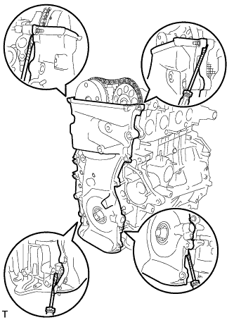
Remove the 12 bolts and 2 nuts.
Remove the timing chain cover by prying the portions between the timing chain cover, cylinder head and cylinder block with a screwdriver.
- NOTICE:
- Be careful not to damage the contact surfaces of the timing chain cover, cylinder head and cylinder block.
- HINT:
- Tape the screwdriver tip before use.
| 48. REMOVE NO. 1 CRANKSHAFT POSITION SENSOR PLATE |
Remove the No. 1 crankshaft position sensor plate.
| 49. REMOVE TIMING CHAIN GUIDE |
Remove the bolt and timing chain guide.
| 50. REMOVE CHAIN TENSIONER SLIPPER |
Remove the bolt and chain tensioner slipper.
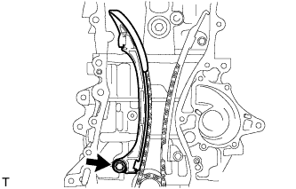
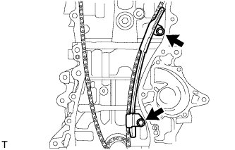
| 51. REMOVE NO. 1 CHAIN VIBRATION DAMPER |
Remove the 2 bolts and No. 1 chain vibration damper.
| 52. REMOVE CHAIN SUB-ASSEMBLY |
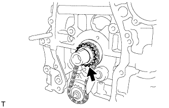
| 53. REMOVE CRANKSHAFT TIMING GEAR OR SPROCKET |
Remove the crankshaft timing gear or sprocket from the crankshaft.
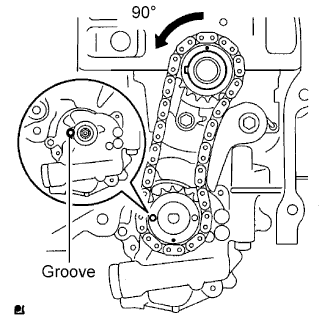
| 54. REMOVE NO. 2 CHAIN SUB-ASSEMBLY |
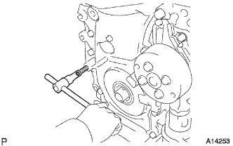
Turn the crankshaft 90° counterclockwise to align the adjusting hole on the oil pump drive shaft sprocket with the groove on the oil pump.
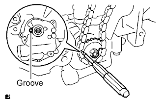
Insert a 4 mm diameter bar into the adjusting hole of the oil pump drive shaft sprocket to lock the gear in position, and then remove the nut.
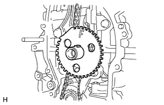
Remove the bolt, chain tensioner plate and spring.
Remove the oil pump drive sprocket, oil pump drive shaft sprocket and No. 2 chain.
| 55. DISCONNECT NO. 1 RADIATOR HOSE |
Disconnect the No. 1 radiator hose from the cylinder head.
| 56. DISCONNECT OUTLET HEATER WATER HOSE |
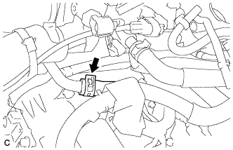
Disconnect the outlet heater water hose.
| 57. DISCONNECT INLET HEATER WATER HOSE |
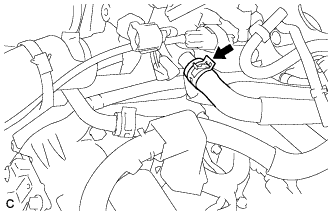
Disconnect the inlet heater water hose.
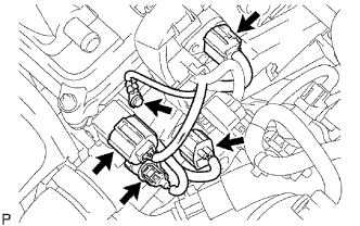
| 58. DISCONNECT ENGINE WIRE |
Disconnect the radio setting condenser connector.
Disconnect the engine oil pressure switch connector.
Disconnect the engine coolant temperature sensor connector.
Disconnect the camshaft position sensor connector.
Remove the bolt and ground cable.
| 59. REMOVE NO. 2 CAMSHAFT |
Using several steps, uniformly loosen and remove the 10 bearing cap bolts in the sequence shown in the illustration.
- NOTICE:
- Uniformly loosen the bolts while keeping the camshaft level.
- HINT:
- Arrange the removed parts in the correct order.
Remove the 5 bearing caps.
Remove the No. 2 camshaft.
Using several steps, uniformly loosen and remove the 10 bearing cap bolts in the sequence shown in the illustration.
- NOTICE:
- Uniformly loosen the bolts while keeping the camshaft level.
- HINT:
- Arrange the removed parts in the correct order.
Remove the 5 bearing caps.
Remove the camshaft.
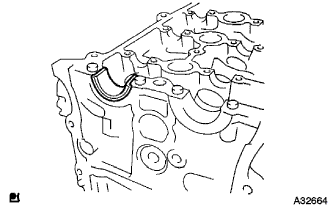
| 61. REMOVE NO. 1 CAMSHAFT BEARING |
Remove the camshaft bearing from the No. 1 camshaft bearing cap.
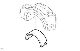
| 62. REMOVE NO. 2 CAMSHAFT BEARING |
Remove the No. 2 camshaft bearing from the cylinder head.
| 63. REMOVE CYLINDER HEAD SUB-ASSEMBLY |
In several steps, uniformly loosen and remove the 10 cylinder head bolts and 10 plate washers with a 10 mm bi-hexagon wrench in the sequence shown in the illustration.
- NOTICE:
- Head warpage or cracking could result from removing the bolts in the wrong order.
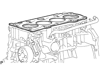
Using a screwdriver with its tip wrapped with tape, pry between the cylinder head and cylinder block, and remove the cylinder head.
- NOTICE:
- Be careful not to damage the contact surfaces between the cylinder head and cylinder block.
| 64. REMOVE CYLINDER HEAD GASKET |